Chapter 4 Operating instructions
Flexi Classic
62 © SICK AG • Industrial Safety Systems • Germany • All rights reserved 8011509/YPP0/2015-10-26
Subject to change without notice
Special applications and
functions
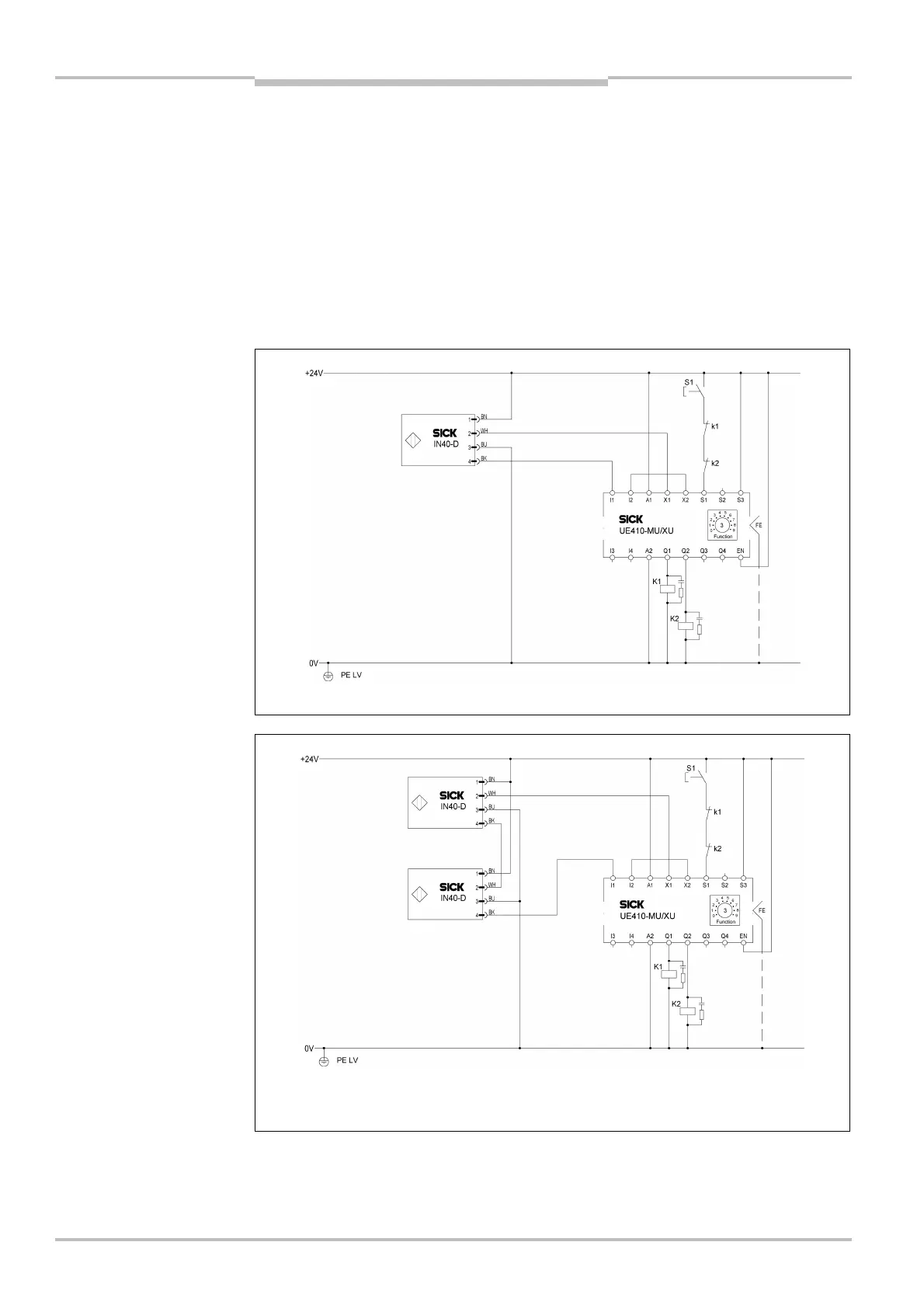
4.2 IN4000 inductive safety switch
IN4000 inductive safety sensors can be connected directly to the inputs of the
UE410-MU/UE410-XU units. The required test signals for the sensors are generated in the
program 3.2 of the UE410-MU/UE410-XU.
Up to nine safety sensors can be cascaded per input.
Inductive safety switches IN4000 cannot be connected to a UE410-GU.
Connection:
A safety sensor/cascade is connected to the input I1 and test output X1.
Further information is available in the IN4000 operating instructions.
Input I2 and test output X2 have to be jumpered. Terminal S2 may not be interconnected.
A selection of the IN4000 safety sensors is available in section 12.2 “Accessories/spare
parts” on page 115.
Note
IN4000
IN4000
Note

 Loading...


