Chapter 3 Operating instructions
Flexi Classic
52 © SICK AG • Industrial Safety Systems • Germany • All rights reserved 8011509/YPP0/2015-10-26
Subject to change without notice
Product description
3.8.1 AND link
The switch settings 1 to 6 of the UE410-8DI add inputs to the UE410-MU/UE410-GU/
UE410-XU modules and link them with AND logic.
If the input conditions I1-I4 and I5-I8 are logical “1”, the AND function is active and the
LED Q
A
or Q
B
is illuminated.
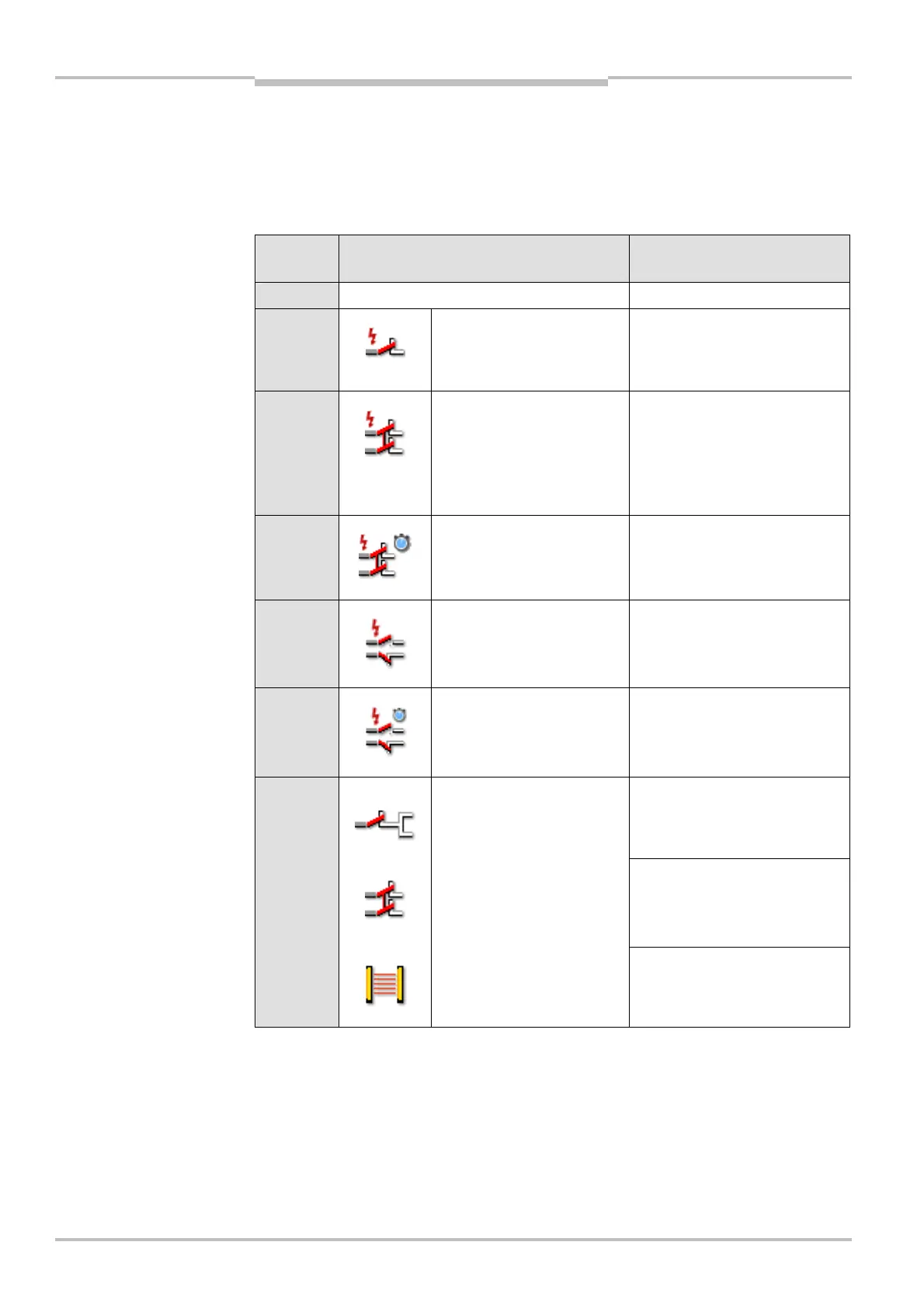
Switch
position
Application Electrical configuration
0 For unused inputs –
1 • Emergency stop button
• Safety switch
• Testable sensors
Single-channel N/C contact
2 • Emergency stop button
• Safety switch
• Switching mat (pressure-
sensitive)
• Flexi Loop
Dual-channel N/C contact,
equivalent, cross-circuit
detecting
3 • Emergency stop button
• Safety switch
• Flexi Loop
Dual-channel N/C contact,
equivalent, cross-circuit
detecting, synchronous time
monitoring 1500 ms
4 • Safety switch
Dual-channel N/C / N/O
contact, complementary, cross-
circuit detecting
5 • Safety switch
• RE300
Dual-channel N/C / N/O
contact, complementary, cross-
circuit detecting, synchronous
time monitoring. 1500 ms
Single-channel N/C contact
Dual-channel N/C contact,
equivalent
6 • Emergency stop button
• Safety switch
• ESPE (e.g. C4000)
Dual-channel semiconductor
output
positions

 Loading...


