Chapter 3 Operating instructions
Flexi Classic
56 © SICK AG • Industrial Safety Systems • Germany • All rights reserved 8011509/YPP0/2015-10-26
Subject to change without notice
Product description
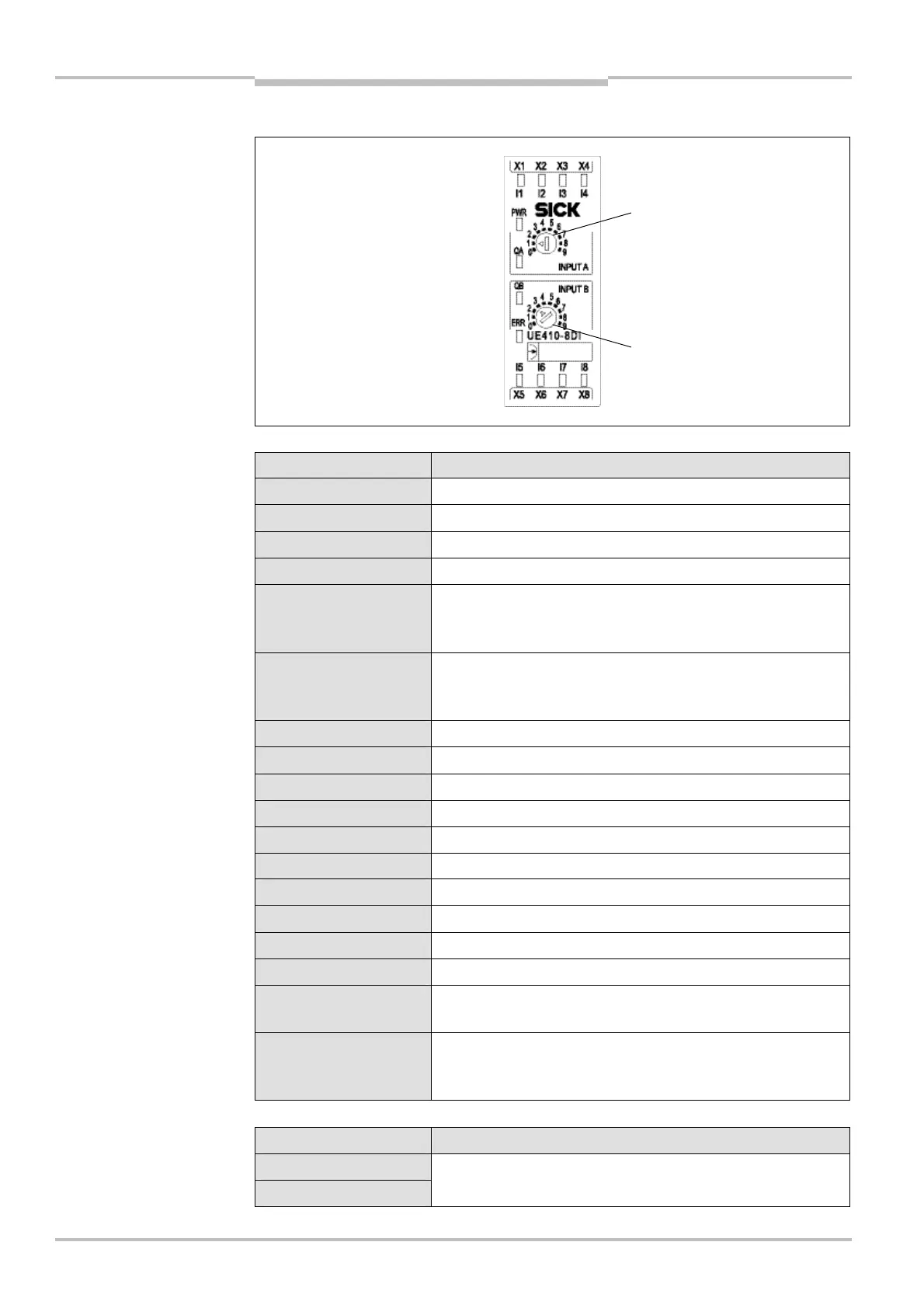
3.8.6 Controls and status indicators
LED indicators Meaning
PWR (green) Supply voltage via safety bus is present.
I1-I8 (green) Logical “1” is applied at the corresponding input.
I1, I2 flash in phase Cross-circuit between I1, I2
I3, I4 flash in phase Cross-circuit between I3, I4
I5, I6 flash in phase
Cross-circuit between I5, I6 or modules with different revision
code (see section 10.2 “Replacement of a module” on
page 93)
I7, I8 flash in phase
Cross-circuit between I7, I8 or modules with different revision
code (see section 10.2 “Replacement of a module” on
page 93)
I1, I2 flash out of phase Process error at I1, I2
I3, I4 flash out of phase Process error at I3, I4
I5, I6 flash out of phase Process error at I5, I6
I7, I8 flash out of phase Process error at I7, I8
I1 or I2 flashing Synchronous time (1500 ms) exceeded
I3 or I4 flashing Synchronous time (1500 ms) exceeded
I5 or I6 flashing Synchronous time (1500 ms) exceeded
I7 or I8 flashing Synchronous time (1500 ms) exceeded
QA (green) Input conditions input A of inputs I1 to I4 are fulfilled.
QB (green) Input conditions input B of inputs I5 to I8 are fulfilled.
ERR (red flashing)
Erroneous operational status on this module, see chapter 10
“Diagnostics” on page 93
ERR (red)
Erroneous operational status on the whole system (the error
is on another module), see chapter 10 “Diagnostics” on
page 93
Switch/button Function
INPUT A
INPUT B
10-step rotary switches for setting an input circuit function
(input group A or B)
and status indicators
indications
operating elements

 Loading...


