Chapter 3 Operating instructions
Flexi Classic
30 © SICK AG • Industrial Safety Systems • Germany • All rights reserved 8011509/YPP0/2015-10-26
Subject to change without notice
Product description
Once the cause of the global emergency stop has been rectified (inputs I1 and I2 are high
again, e.g. protective field clear), then the UE410-GU on which the global emergency stop
was originally triggered signals on output Q2 the status Reset required with a signal
flashing at 1 Hz.
Reset
A global emergency stop can only be reset manually. The reset must be undertaken on the
same module on which the global emergency stop was triggered.
Once the global cut-off path for this module is closed again (inputs I1 and I2 are high
again, e.g. protective field clear) and the reset button on this module is then operated, the
safety output Q1 on this module as well as the outputs O
P
and O
N
switch to high again.
The following conditions are to be noted for the reset:
• Only the falling edge is evaluated.
• The minimum actuation time for the reset button is ≥ 50 ms.
• The maximum actuation time for the reset button is ≤ 5 s.
If one of these criteria is not met, the emergency stop is not reset.
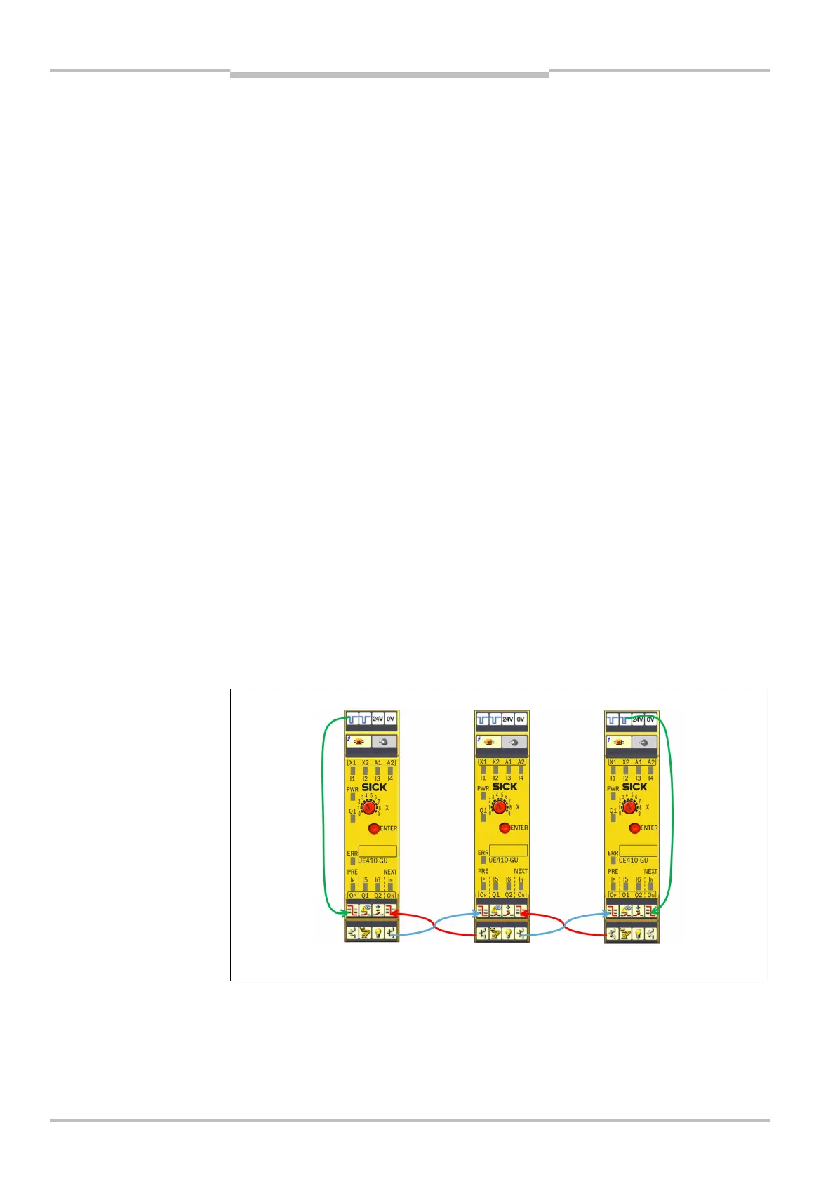
Wiring of the modules
To connect several UE410-GU modules together, the input I
N
on the previous UE410-GU
must be connected to the output O
P
on the next UE410-GU and the output O
N
on the pre-
vious UE410-GU must be connected to the input I
P
on the next UE410-GU.
For the specification of the connection cable please refer to the data sheet in sec-
tion 11.1.2 “UE410-GU module” on page 101.
The first and last UE410-GU in an emergency stop system act as end modules. An end
module is a UE410-GU that has only one neighboring station. These modules are defined
by the wiring of the outputs X1 and X2.
• The end module without PRE is defined by wiring X1 to I
P
.
• The end module without NEXT is defined by wiring X2 to I
N
.
This wiring is saved with the configuration and checked each time on switching on.
UE410-GU modules

 Loading...


