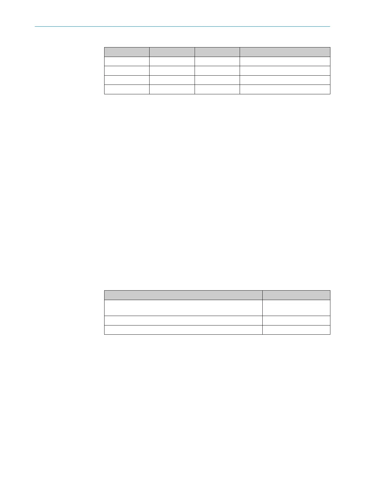
Table 6: Valid combinations of input signals for three or four monitoring cases
IN 1 IN 2 IN 3 Monitoring case
1 0 0 1
0 1 0 2
0 0 1 3
1 1 1 4
1
1
This combination is only valid if four monitoring cases are configured.
Sequence of monitoring cases
T
he safe multibeam scanner does not check the order in which the individual monitor‐
ing cases are activated. If necessary, you must ensure the required sequence of moni‐
toring cases externally, e.g. by the device that provides the input signals for monitoring
case switching.
Invalid signals
If a combina
tion of input signals cannot be associated with a monitoring case, the safe
multibeam scanner outputs an error of the category “Recoverable error”.
As soon as the combination of the input signals is valid and can be associated with a
monitoring case, the safe multibeam scanner switches back to normal operation and
activates the corresponding monitoring case.
Input delay
Y
ou can configure a switch-on delay between 10 and 500 ms. After the safe multibeam
scanner has detected a change in input states, the inputs are ignored for the duration
of the configured switch-on delay.
If the control device that you use to switch the static control inputs cannot switch to the
appropriate input condition within 10 ms (for example because of the switch’s bounce
times), you need to increase the input delay. The selected input delay must be large
enough to allow your control device to switch to the new input condition within this time.
Table 7: Empirical values for the input delay
Switching method Input delay required
Electronic switching via a controller, complementary electronic out‐
put
s with 0 ms to 10 ms bounce time
10 ms
Tactile controls (relays) 30 ms to 150 ms
Control via independent sensors 130 ms … 500 ms
Further topics
•
"E
lectrical installation", page 39
•
"Technical data", page 73
•
"Monitoring cases", page 54
4.4.4 Universal output
The universal output (Uni-O) can be assigned various signals for non-safety applica‐
t
ions, e.g., warning field interruption, contamination or error. The signal level for the
universal output is configurable.
Further topics
•
"E
lectrical installation", page 39
•
"Technical data", page 73
•
"Inputs and outputs, local", page 53
PROJECT PLANNING 4
8025936/2021-01-08 | SICK O P E R A T I N G I N S T R U C T I O N S | scanGrid2 I/O
31
Subject to change without notice

 Loading...


