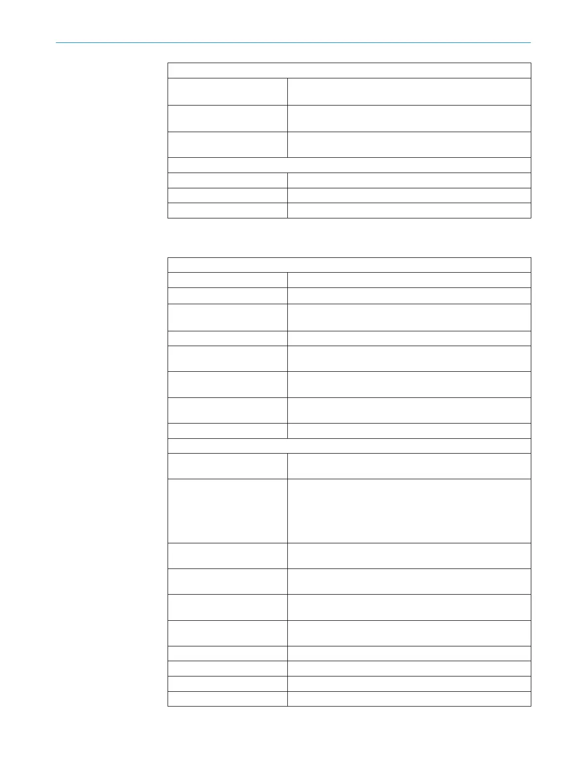
Length of cable for system connection
1)
In a single system with a
suppl
y voltage U
V
≥ 12 V
≤ 30 m
In a single system with a
suppl
y voltage U
V
< 12 V
≤ 12 m
In a cascade (total length of
all c
ables)
≤ 12 m
USB interface for configuration and diagnostics
Connection type USB 2.0 Type-C
Transfer rate 12 Mbit/s (Full Speed)
Length of cable ≤ 5 m
1)
For a cable cross-section of at least 0.25 mm
2
.
Table 20: Electrical data
Operating data
Protection class III (IEC 61140)
Supply voltage U
V
24 V DC (8.4 V … 30 V DC) (SELV/PELV)
1)
2)
Supply voltage U
V
in a c
as‐
cade
24 V DC (14 V … 30 V DC) (SELV/PELV)
1)
2)
Residual ripple ± 10%
3)
Power consumption (maxi‐
mum v
alue)
≤ 3 W
Average power consumption
dur
ing a scan cycle
≤ 2 W
Power consumption in sleep
mode
≤ 1 W
Power-up delay ≤ 2 s
Output signal switching devices (OSSDs)
Type of output 2 semiconductors per OSSD pair, short-circuit protected
4)
,
cr
oss-circuit monitored.
Output mode You can configure the output mode globally for both OSSDs.
The OSSDs can output the signals in the following modes:
•
PNP: Default setting for all applications (including safety
applications)
•
NPN: For non-safety applications only
Output voltage for ON state
(H
IGH) in PNP mode
(U
V
- 2.25 V) ... U
V
Output voltage for OFF state
(LOW) in PNP mode
0 V … 2 V
Output voltage for ON state
(L
OW) in NPN mode
0 V ... 2.25 V
Output voltage for OFF state
(HIGH) in NPN mode
(U
V
- 2 V) ... U
V
Output current for ON state ≤ 200 mA
Leakage current ≤ 250 µA
5)
Load inductance ≤ 2.2 H
Load capacity ≤ 1 μF
13 TECHNICAL DATA
74
O P E R A T I N G I N S T R U C T I O N S | scanGrid2 I/O 8025936/2021-01-08 | SICK
Subject to change without notice

 Loading...


