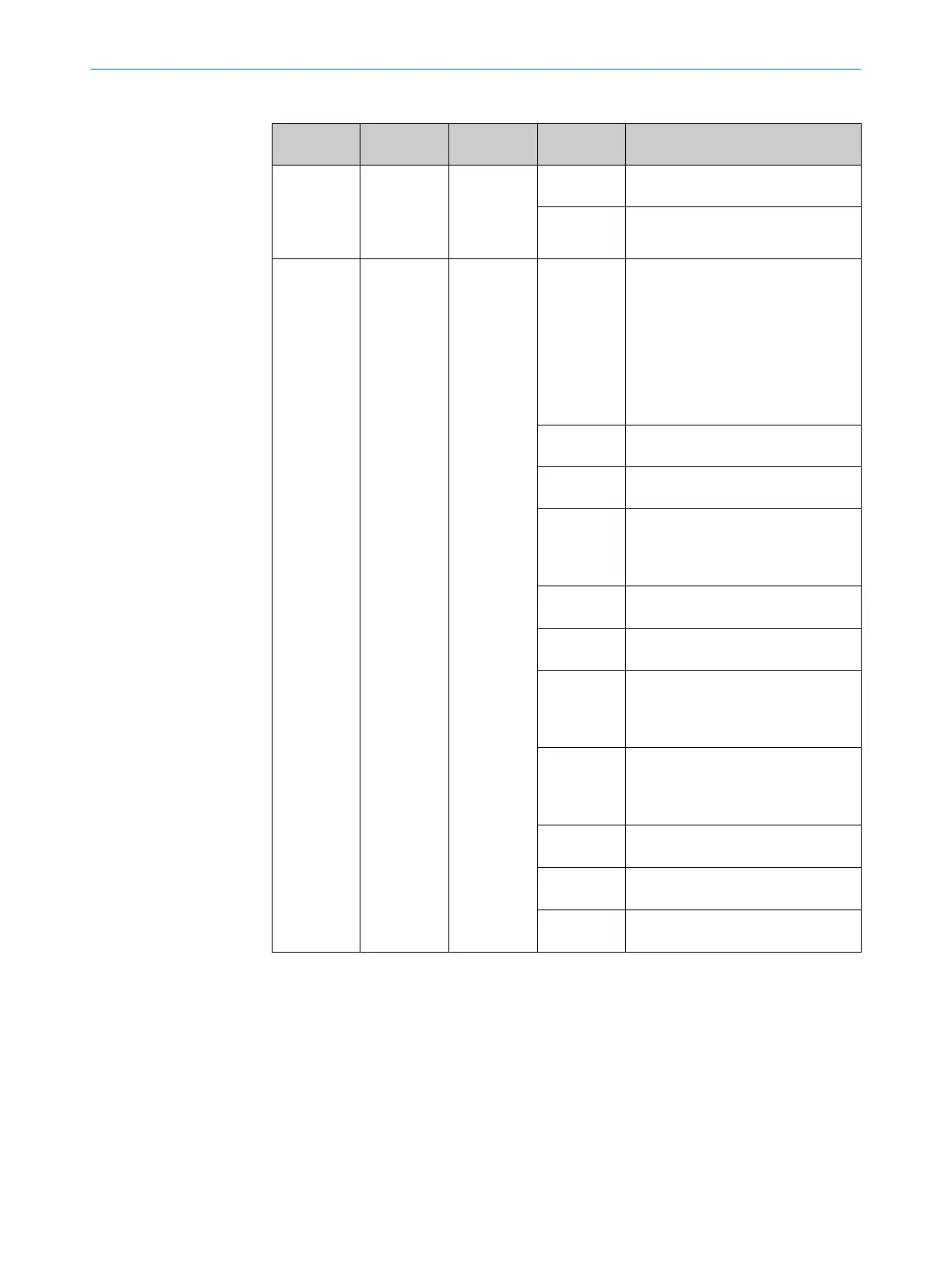
Table 15: LEDs
Number Name Function LED state
(c
olor)
Meaning
!
OSSD-LED Indicates the
O
SSD state
that the
device out‐
puts.
O Gr
een
ON state: The safety outputs are in
t
he ON state.
O R
ed
OFF state: At least one safety output
is in t
he OFF state.
"
STATE LED Indicates the
status of the
device.
O Gr
een
ON state: The device is in normal
mode
.
The device has been configured cor‐
rectly and the configuration is veri‐
fied.
There is no error, no warning and
no interruption of the active warning
field.
The restart delay is not active.
O Y
ellow
Interruption of the active warning
f
ield
o Of
f
Sleep mode or safety function
s
topped
Ö F
lashing
red and
green alter‐
nately
Device was identified in Safety
D
esigner.
Ö F
lashing
red
Device error (see "Er
ror categories",
page 66)
Ö F
lashing
yellow (3 Hz)
Recoverable error (see "Er
ror cate‐
gories", page 66)
Ö F
lashing
red and yel‐
low alter‐
nately
The device is not configured or an
er
ror has been detected in the con‐
figuration.
Ö F
lashing
yellow and
green alter‐
nately
The device is configured, but the con‐
f
iguration is not verified.
Ö F
lashing
green (3 Hz)
Restart delay active
Ö F
lashing
yellow (1 Hz)
Contamination warning
Ö F
lashing
green (1 Hz)
Test mode (for testing an unverified
conf
iguration)
o LED of
f. Ö LED flashes. O LED illuminates.
Complementary information
T
he display elements are only used for diagnostic purposes and are not safety-relevant.
Even if the status indicators are displaying incorrect information or have failed, the safe
multibeam scanner will still supply the signals required for the safety function.
OPERATION 9
8025936/2021-01-08 | SICK O P E R A T I N G I N S T R U C T I O N S | scanGrid2 I/O
63
Subject to change without notice

 Loading...


