97
8014084/ZWT7/V3-1/2020-06 | SICK OPERATING INSTRUCTIONS | TRANSIC111LP
Subject to change without notice
SPECIFICATIONS 10
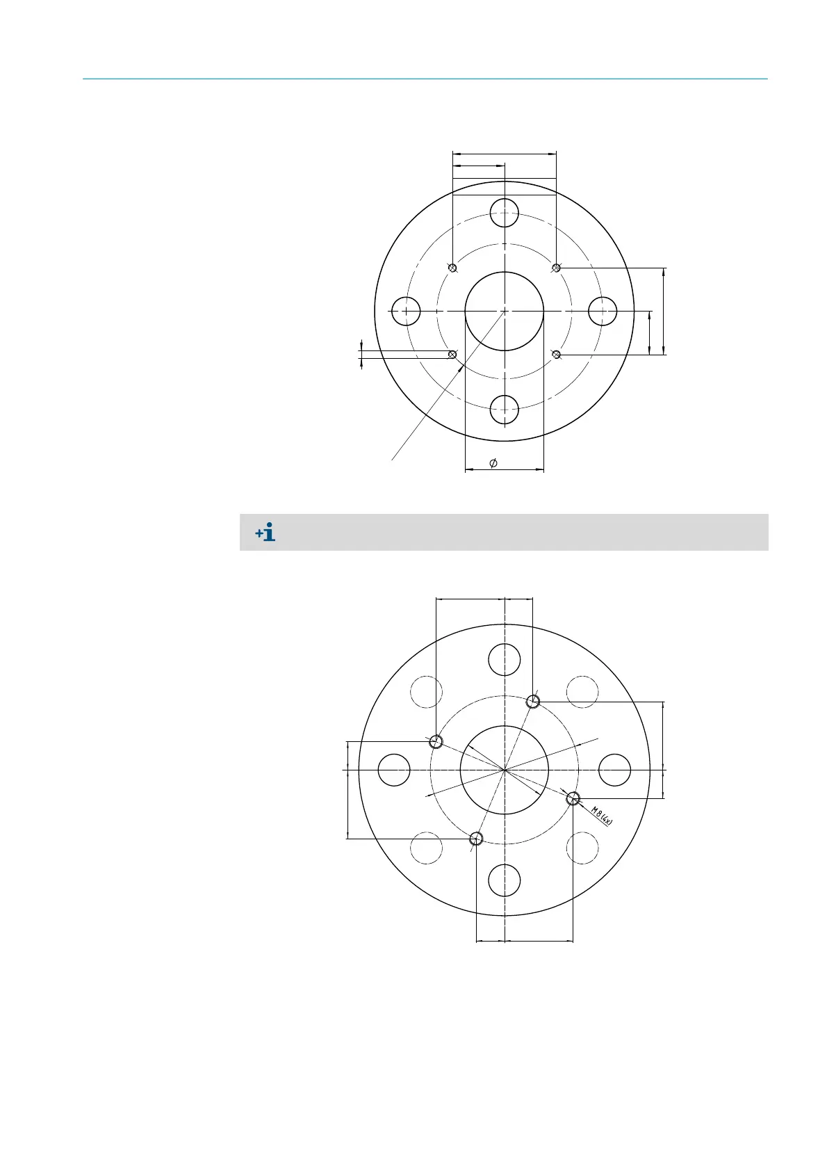
Fig. 43: Mounting flange with M5 bolts suitable up to 0.5 bar
Fig. 44: Mounting flange with M8 bolts suitable for PS=10 bar
33
27.5
R43
55
66
50
4 x M5
(2.6)
(1.08)
(1.97)
(1.3)
(2.16)
All specifications in mm (inches)
When installing with a tube with an outer diameter > 80 mm, do not drill M5 through-
holes to prevent leakage from the process.
38,8 (1.53)
38,8 (1.53)
38,8 (1.53)
38,8 (1.53)
16,1 (0.63)
16,1 (0.63)
16,1 (0.63)
16,1 (0.63)
Ø 84
(3.31)
Ø 50
(1.97)
All specifications in mm (inches)