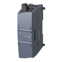
AddFEM
Commissioning / Operation / Maintenance
5-45
AddFEM
C79000–G8076–C900–03
5.6 Detailed Description of the Driver Function Blocks
The following sections describe the four driver function blocks FEM_AI, FEM_AO,
FEM_DI, FEM_DO in detail.
Note
The driver function blocks can be configured optionally ..
a) ...with SIMATIC CFC (Continuous Function Chart) or ..
b) ...exclusively with SIMATIC S7 STL (statement list).
If you carry out configuration with CFC (Case a), installation in the various priority
classes is carried out automatically by the configuration system.
5.6.1 FEM_AI – Analog Input
The following OBs must call the function block FEM_AI:
a) Watchdog interrupt OB for cyclic operation (for example OB 32).
b) In addition the block has to be called in the OB70, OB72, OB80, OB82, OB83,
OB85, OB86, OB100 and OB121 in order to intercept special functions such
as the start–up, peripheral errors, timeout, etc.
Area of Application
The block is the header block for the supply and disposal of the AddFEM.
Functional Description
The block detects the 12 analog inputs of the AddFEM module, converts the stan-
dardized fixed–point values, depending on the range limits, into REAL values and
makes the values available at the output bar.
The block reads the standardized fixed–point values of the AddFEM module and
maps these to the physical range.
The physical value is output in REAL format at the block output parameters.
If the switch SIMUAIx = 1, not the value of the AddFEM is output at the block out-
put, but the simulation value AIx_SIM.
Note
SIMUAIx means SIMUAI<Channel Number 1 to 12> e.g. SIMUAI1.
Artisan Technology Group - Quality Instrumentation ... Guaranteed | (888) 88-SOURCE | www.artisantg.com

 Loading...


