Technical Data AddFEM
4-4
AddFEM
C79000–G8076–C900–03
Digital Inputs
Number of inputs 12
Type of input to IEC IEC 61131–2 Type 1
Voltage range –30 V...+30 V DC
0-signal level –30 V...+5 V
1-signal level +11 V...+30 V
48-V contact voltage No
Connection of BEROs possible Yes
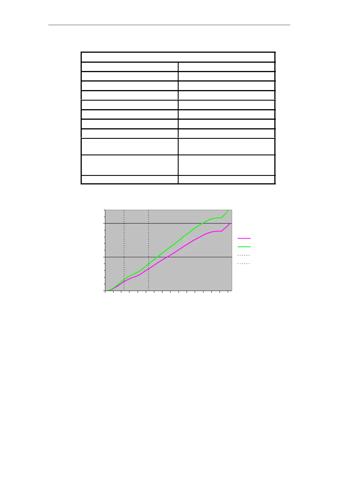
Minimum current at input voltage 5 mA at 11 V (refer to Fig. 4-1)
Delay time (TID) 50 µs for signal transitions from 0 to 1
50 µs for signal transitions from 1 to 0
Display The converted values read by the internal mi-
cro controller unit are displayed at the LEDs
on the front.
Configuration of the terminals Refer to Appendix A, connector X6, Page A-2
10 mA
5 mA
0 mA
0102030
Ie min
Ie max
Switching point
min.
Switching point
max.
Input characteristic curve of digital inputs
Figure 4-1 Characteristic curve image for digital inputs
Artisan Technology Group - Quality Instrumentation ... Guaranteed | (888) 88-SOURCE | www.artisantg.com
 Loading...


