AddFEM
Mode of Operation
3-19
AddFEM
C79000–G8076–C900–03
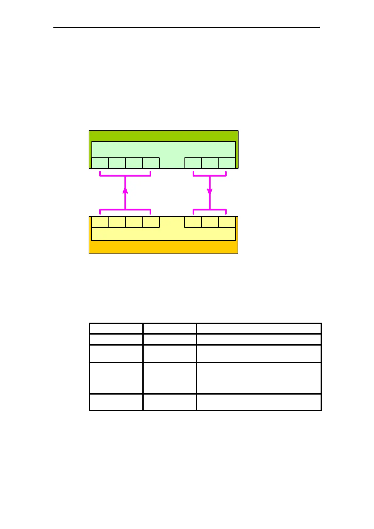
Signals for Controlling The Redundancy Logic
Signals for controlling the redundancy logic are exchanged via the PROFIBUS DP
user data messages. A driver block with implemented redundancy logic is available
for SIMATIC S7.
Note:
The redundancy logic has to be configured for operation with other Hosts.
Host
Driver with redundancy logic
AddFEM
Redundancy logic
MRS FG KFG
ZRV MRV LZ
ZRV MRV LZLDA
MRS FG KFG LDA
PROFIBUS
Figure 3-10 Signals for controlling the redundancy logic
Signals from the AddFEM to the Host
Signal name Meaning Value
FG Error weighting For structure refer to Chapter 4
KFG Channel error
weighting
Number of faulty I/O channels
LDA Sign of life + active
PROFIBUS DP
channel
Bit 0 – 3: Return SoL to Host
Bit 4 – 6: Reserve
Bit 7: 0 = DP channel A is active
1 = DP channel B is active
MRS Master/Reserve
status
0 = Reserve; 1 = Master
Artisan Technology Group - Quality Instrumentation ... Guaranteed | (888) 88-SOURCE | www.artisantg.com
 Loading...


