Do you have a question about the Siemens Add 7 AddFEM and is the answer not in the manual?
Describes the Add 7 product family and the AddFEM module's specific roles.
Details applications involving DPV1 services for front end functions.
Information on controlling the AddFEM via driver blocks for SIMATIC S7.
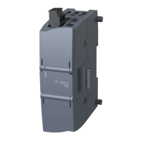
Overview of the AddFEM module's internal components and housing.
Description of the module's switches, LEDs, and their functions.
Details on the various connectors and interfaces on the AddFEM module.
Explains the module's operating states and LED indications during startup.
Covers self-tests, self-monitoring, and delayed shutdown mechanisms.
Details the functionality of speed detection with rotation recognition.
Describes the four available system configurations and operating modes.
Explains redundancy principles, master/reserve roles, and optical-fiber coupling.
Details the redundant PROFIBUS DP interfaces and their role in system redundancy.
Explains how 'signs of life' are used for monitoring and changeover.
Describes the operating states and logic for redundant module operation.
Details the use of Front End Functions (FEF) for preprocessing tasks.
Provides general specifications including dimensions, mass, and input voltage.
Details safety approvals, operating conditions, and electromagnetic compatibility.
Defines the structure of parameterization, input, and output telegrams.
Explains the format and meaning of diagnostic messages and error indicators.
Instructions for physically installing the AddFEM module via DIN rail or screws.
Procedures for setting the PROFIBUS DP address using switches or SIMATIC Manager.
Details the function of LEDs, switches, and their operational status meanings.
Guide to configuring the AddFEM using PROFIBUS configuration tools.
In-depth explanation of FEM_AI, FEM_AO, FEM_DI, and FEM_DO driver function blocks.
Procedures for handling failures and exchanging redundant AddFEM modules.
Pin configuration details for the X4 connector (Analog Outputs/Inputs).
Pin configuration details for the X6 connector (Digital Inputs/Counters).
| Brand | Siemens |
|---|---|
| Model | Add 7 AddFEM |
| Category | Control Unit |
| Language | English |


 Loading...