Design AddFEM
2-4
AddFEM
C79000–G8076–C900–03
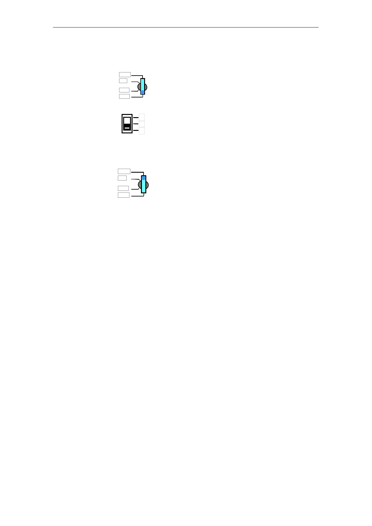
RUN P
MRES
RUN
STOP
Momentary–contact position of the key–operated switch.
Is used during the setting procedure for the bus addresses.
2
1
0
Position 0 – Momentary–contact position spring–loaded:
The PROFIBUS–DP–station addresses are displayed via the DI
signal LEDs in hexadecimal forms. The least significant bit is at the
top! The display is activated for approx. 5 seconds.
Position 1 – Latched position: Position of rest
Position 2 – Latched position: No function
RUN P
MRES
RUN
STOP
Note:
Reserved for function extensions.
The key cannot be withdrawn in this position.
Artisan Technology Group - Quality Instrumentation ... Guaranteed | (888) 88-SOURCE | www.artisantg.com
 Loading...


