Commissioning / Operation / Maintenance AddFEM
5-10
AddFEM
C79000–G8076–C900–03
Table 5-1 Setting the PROFIBUS–DP Address for Bus A via Key–operated and Slide Switches
Seq.
No.
Operation Handling
(key–operated and
slide switches)
Display/Reaction Next step,
if ...
1 Preparation of
AddFEM for adjust-
ment procedures.
Turn key–operated
switch to the ”STOP”
position and press
slide switch to spring
position 0.
2
1
0
MRES
RUN
STOP
RUN P
Status–LED ”USR1” flashes.
Status-LED ”USR1” flickers.
USR1
USR1
...wait until
status LED
”USR1”
flickers!
Then pro-
ceed with
Step 2.
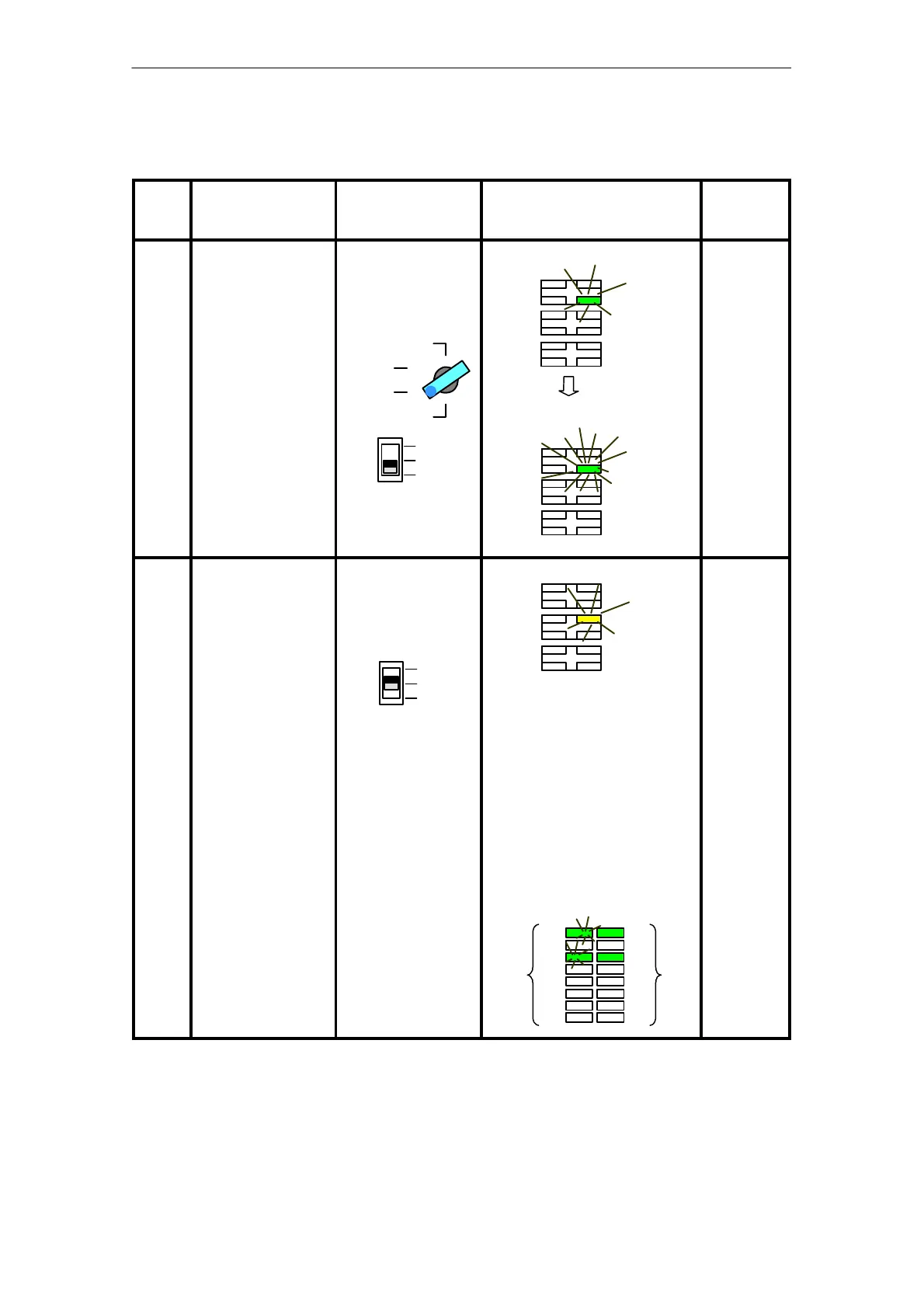
2 Function mode 1,
set ”DP address A”.
Release the slide
switch
The slide switch
springs back to Posi-
tion 1
2
1
0
Status LED “SSA” flashes.
SSA
The currently set addresses for
DP A (left LEDs 1 to 8 flashing)
and DP B (right LEDs 9 to 16 sta-
tic) are indicated at the 16 signal
LEDs in binary form.
LED 1 has the value 2
0
.
LED 2 has the value 2
1
.
etc.
The address 5 is set respectively
for DP A and DP B in the follo-
wing example:
1
8
9
16
Adr. DP BAdr. DP A
Continue
with Step 3
...
Artisan Technology Group - Quality Instrumentation ... Guaranteed | (888) 88-SOURCE | www.artisantg.com
 Loading...


