AddFEM
Mode of Operation
3-17
AddFEM
C79000–G8076–C900–03
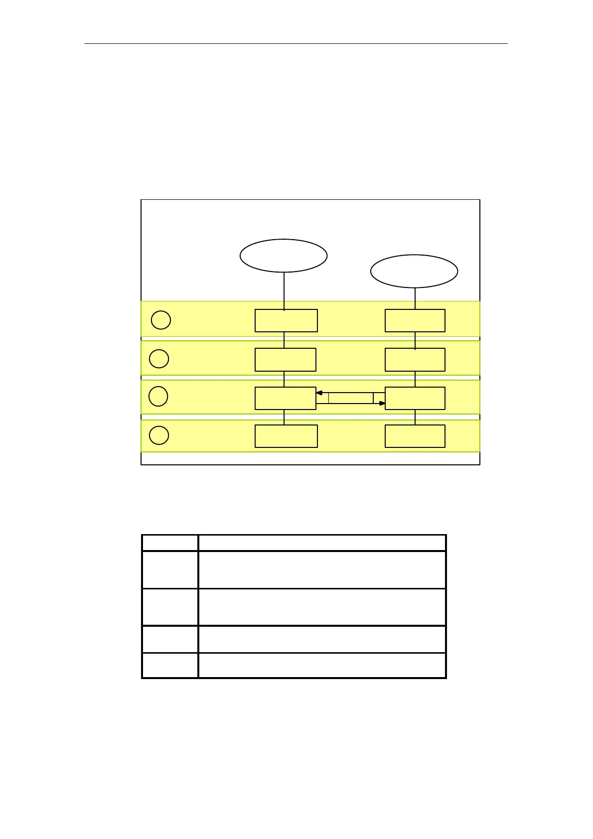
3.3.5 Redundant AddFEMs
Operating States at Module Redundancy
Generally both AddFEMs have equal rights so that each AddFEM can be either the
master or the reserve. In the following figure it is assumed that AddFEM(1) takes
over the master state.
System state
Start–up
1.
START–UP START–UP
Solo mode
2.
LINK–UP
ACTIVE
Interfacing
3.
LINK–UP
ACTIVE
LINK–UP
PASSIVE
Redundant
4.
RUN ACTIVE RUN PASSIVE
Update
RESERVE
MASTER
POWER–ON/Reset
AddFEM(1)
POWER–ON/Reset
AddFEM(2)
START–UP
Figure 3-9 Operating states from POWER–ON to RUN
Table 3-3 Explanations on the operating states
Item
Description
1. After the supply voltage has been switched on or after a
hardware reset the AddFEM is in the START–UP state after
an initialization phase.
2. If the start–up is successfully, the master AddFEM(1)
changes to solo mode. AddFEM(2) has not yet exited to
START–UP state.
3. Checking and updating the reserve AddFEM(2) is carried
out again.
4. After the LINK–UP coupling the master and reserve
AddFEMs are in the RUN state.
Artisan Technology Group - Quality Instrumentation ... Guaranteed | (888) 88-SOURCE | www.artisantg.com
 Loading...


