Design AddFEM
2-2
AddFEM
C79000–G8076–C900–03
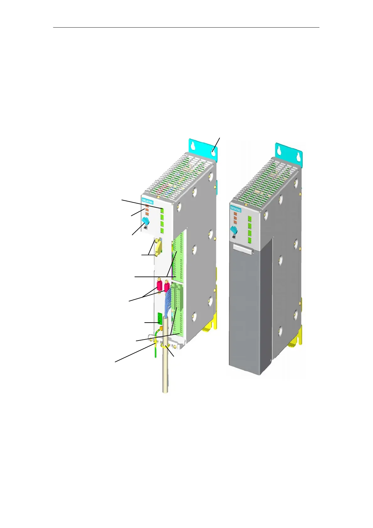
2.1 Structure of the AddFEM
The AddFEM encompasses the following units in a stainless–steel housing: Power
supply unit, processors, PROFIBUS DP interfaces, interfaces for process input
and output signals, redundancy and service interface as well as switches and sta-
tus displays.
All the connection elements are covered with a cover on which the connection de-
signations are printed.
AddFEM
without cover
AddFEM
with cover
Keyhole for wall mounting
Strain relief
Signal LED
Operating and er-
ror status LED
Operating mode
Redundancy and
service interface
Process signals
“Analog”
Redundant
PROFIBUS DP
Module supply
24 V DC
Process signals
“Digital”
Grounding
key–operated switch
Figure 2-1 AddFEM with and without cover
The AddFEM module can be mounted optionally on mounting rails or via fastening
sheets to the wall.
The overall dimensions without fixing elements are (W x H x D):
75 x 290 x 190 mm
Artisan Technology Group - Quality Instrumentation ... Guaranteed | (888) 88-SOURCE | www.artisantg.com
 Loading...


