AddFEM
Design
2-9
AddFEM
C79000–G8076–C900–03
PROFIBUS–DP Connection X3A and X3B
The AddFEM disposes of two PROFIBUS connections which are used for commu-
nication with the automation processor.
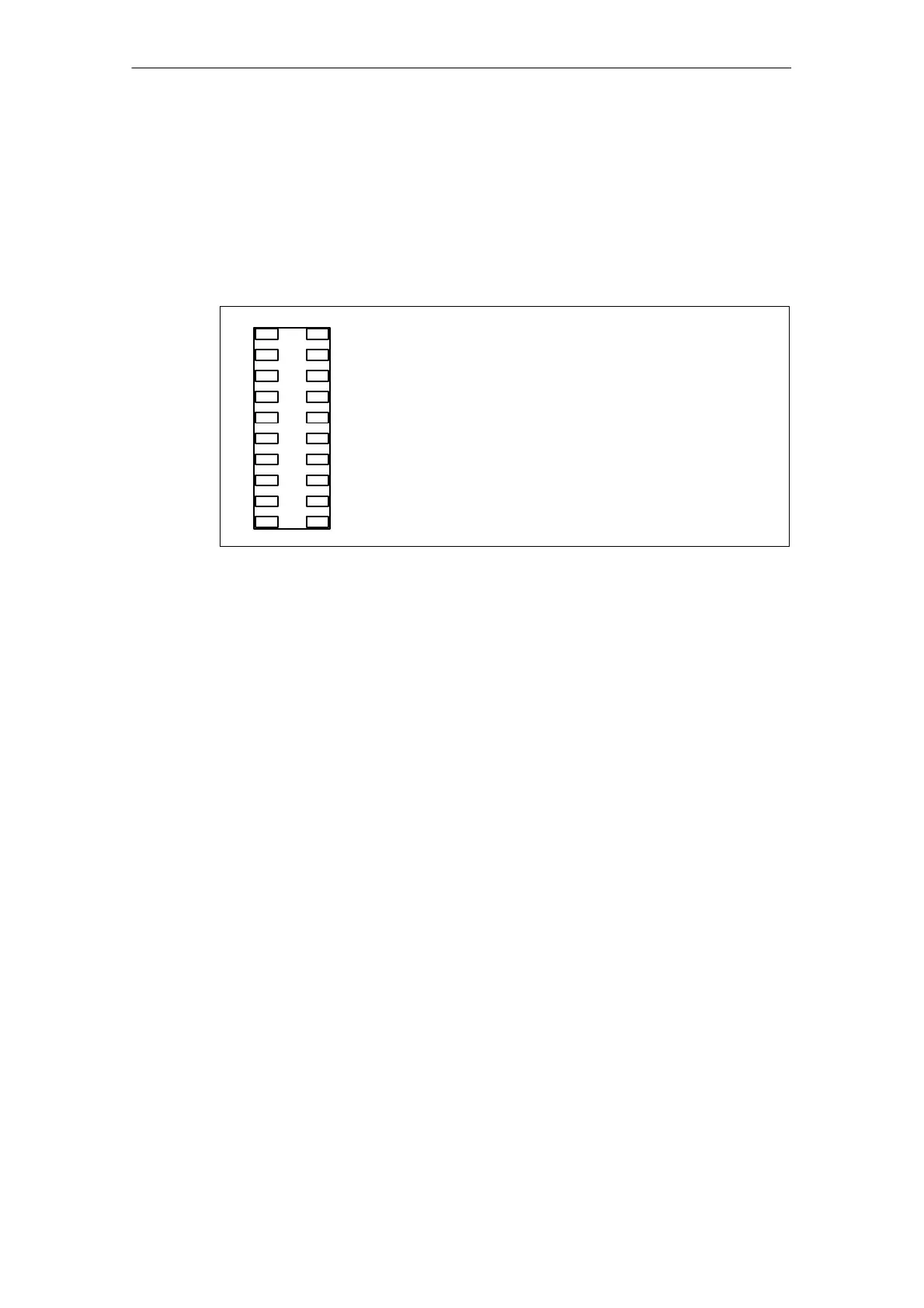
Front Connectors X4 – X7
1 11
2010
The 4 connectors on the panel have the same structure and
the same numbering.
The two upper connectors (X4, X5) are reserved for the ana-
log signals. The two lower connections (X6, X7) have the
digital signals and the speed detection signals assigned.
For the configuration please refer to the tables in Appendix A.
A B
Figure 2-5 Front connector
Of the 12 analog inputs 6 can be used optionally as power inputs or as voltage in-
puts. The remaining 6 analog inputs can only be used as current inputs.
The 16 digital outputs can also be used as digital inputs.
Of the 15 digital inputs 3 can be used as counting pulse inputs for speed detection
with/without recognition of the direction of rotation. In the case of speed detection
with recognition of the direction of rotation counting pulse input 1 detects the lea-
ding signal while counting pulse input 2 detects the lagging signal.
Artisan Technology Group - Quality Instrumentation ... Guaranteed | (888) 88-SOURCE | www.artisantg.com
 Loading...


