AddFEM
Design
2-5
AddFEM
C79000–G8076–C900–03
LED
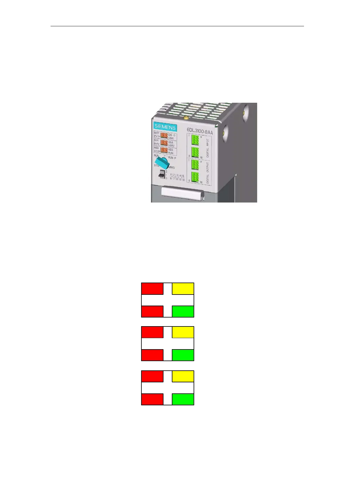
Above the key–operated switch there are 3 LED units with 4 LEDs each for error
displays (left) and status displays (right). The logical states of the digital inputs
and outputs are displayed by means of 32 operating state LEDs, which are posi-
tioned on the right, next to the error/status LEDs and the two switches.
Positioning of
the LEDs and
operating ele-
ments
Figure 2-2 AddFEM operating elements
Meaning of the
Error/Status
LEDs
The error/status LEDs are divided into 3 LED units with 4 LEDs each.
The error LEDs are position on the left, the status LEDs are on the right.
Green
Yellow
Red
Red
Green
Yellow
Red
Red
Green
Yellow
Red
Red
INTF
EXTF
BUSF1
BUSF2
RED
STOP
DISO
USR1
SSA
USR2
RES
RUN
Artisan Technology Group - Quality Instrumentation ... Guaranteed | (888) 88-SOURCE | www.artisantg.com
 Loading...


