Mode of Operation AddFEM
3-12
AddFEM
C79000–G8076–C900–03
Redundancy Nodes
Redundancy nodes represent the fault tolerance of systems with components
which are available several times. The independence of a redundancy node is gi-
ven when the failure of a component does not cause any limitations in reliability in
other nodes or in the complete system. In a “1–out–of–2” system a component of
the redundancy node can fail without impairing the functional capability of the com-
plete system.
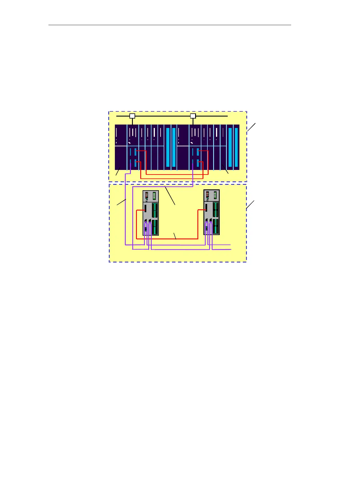
Fig. 3-5 System configuration with two redundancy nodes
LAN
AP A
AP B
DP A
DP B
Redundancy node
Redundancy node
Add FEM
RK
RK: Redundancy coupling
AP
The two automation processors (AP A and AP B) in Fig. 3–5 execute the same
application software, for example, the turbine control function, synchronously and
cyclically. One system (AP A or AP B) is the “master” and actively controls the out-
puts. When faults occur in the master system, a changeover takes place automati-
cally and smoothly to the reserve system. The redundancy status and additionally
update information are exchanged between AddFEM A and AddFEM B via the red-
undancy coupling (RED coupling).
Artisan Technology Group - Quality Instrumentation ... Guaranteed | (888) 88-SOURCE | www.artisantg.com
 Loading...


