Technical Data AddFEM
4-8
AddFEM
C79000–G8076–C900–03
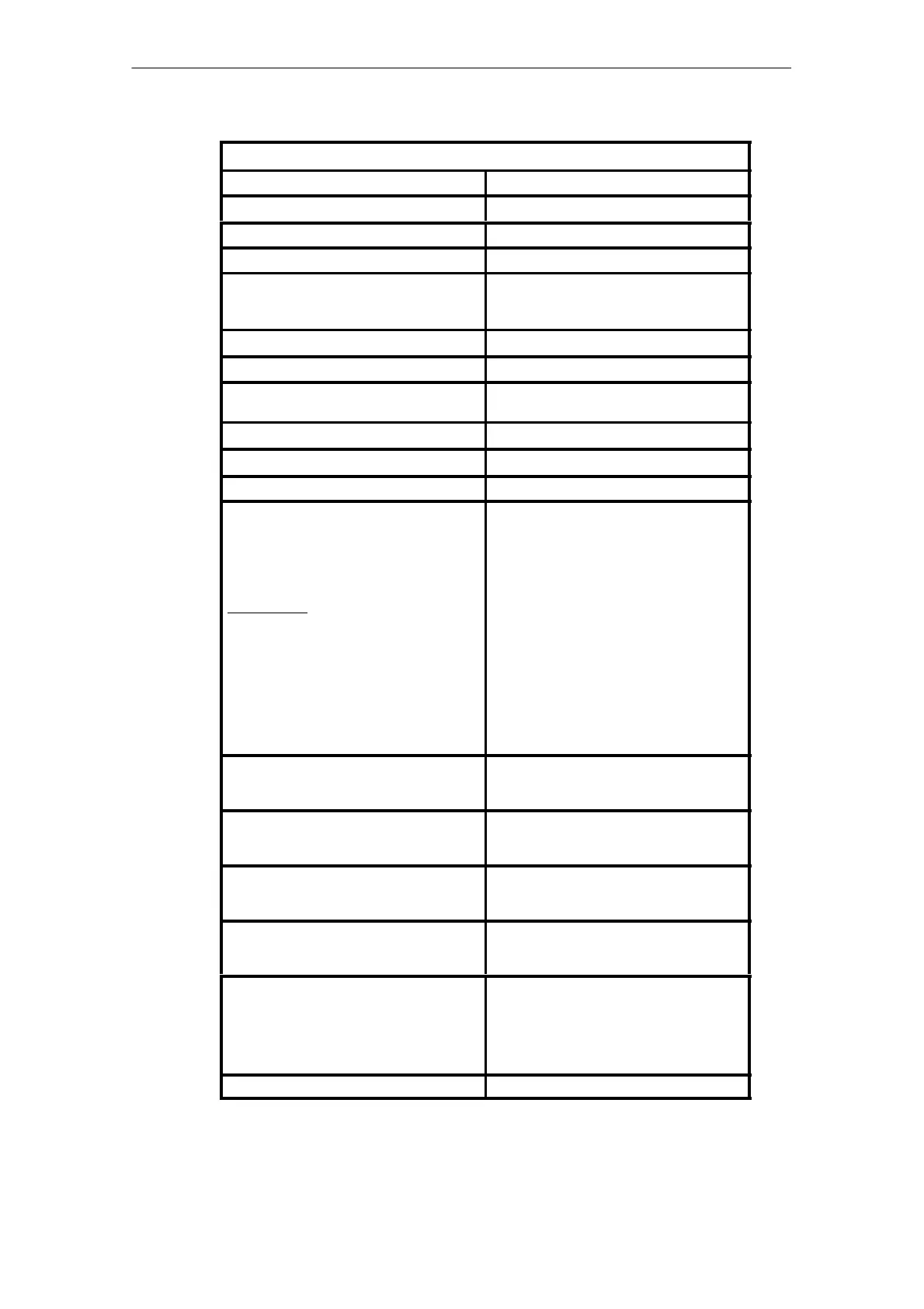
Digital Outputs
1)
Number of outputs 16 digital semiconductor outputs
Nominal output voltage 24 V DC
Output voltage at 0 signal < 1V
Output voltage at 1 signal Supply voltage –2 V
Max. output current 500 mA
Parallel connection of outputs for higher cur-
rents is possible.
Output current at 100% coincidence factor 500 mA
Total output current 8A
Effects of multiple overloads on multiple circuit
modules
None
Short–circuit to ground monitoring Yes
Short–circuit strength Yes
Max. lamp load per output 5W
Inductive loads
Typical values:
Maximum inductivity at I v 500 mA
Connection of inductive loads is possible. Inte-
grated suppressor diodes with a higher extinc-
tion voltage of 39 V than the normal free–
wheeling diode lead to rapid disconnection of
the current and thus of the actuating element.
However, the maximum extinction current (1
W) may not be exceeded.
8 H (without external suppressor diode)
Maximum inductivity at I v 500 mA
and f v 1Hz
Maximum inductivity at I t 250 mA
and any f
Maximum inductivity at external suppressor
diode
8H
without external suppressor diode
Unlimited
Unlimited
Output delay time (TQD, dead time) from com-
mand output to response of the output (begin-
ning of the current rise)
20 µs for signal transitions from 0 to 1
20 µs for signal transitions from 1 to 0
Output response time (TQT) from command
output until the full output current is reached at
500 mA
50 µs for signal transitions from 0 to 1
50 µs for signal transitions from 1 to 0
Behavior of the outputs at interruption of the
operation controlled by the main processing
unit
The outputs are de–activated
Behavior of the outputs at collapsing and inter-
ruptions of the supply voltage L1+ resp. L2+ at
X7/1 resp. X7/11
The output voltage of the outputs follows the
supply voltage.
Display The voltage level of the digital outputs are de-
tected via additional module–internal digital
inputs, converted and read by the internal mi-
cro controller unit. The micro controller unit
displays these read–back states at the LED
on the front.
Configuration of the terminals Refer to Appendix A, connector X7, Page A-2
1)
Digital outputs can also be used as digital inputs!
Artisan Technology Group - Quality Instrumentation ... Guaranteed | (888) 88-SOURCE | www.artisantg.com
 Loading...


