Technical Data AddFEM
4-24
AddFEM
C79000–G8076–C900–03
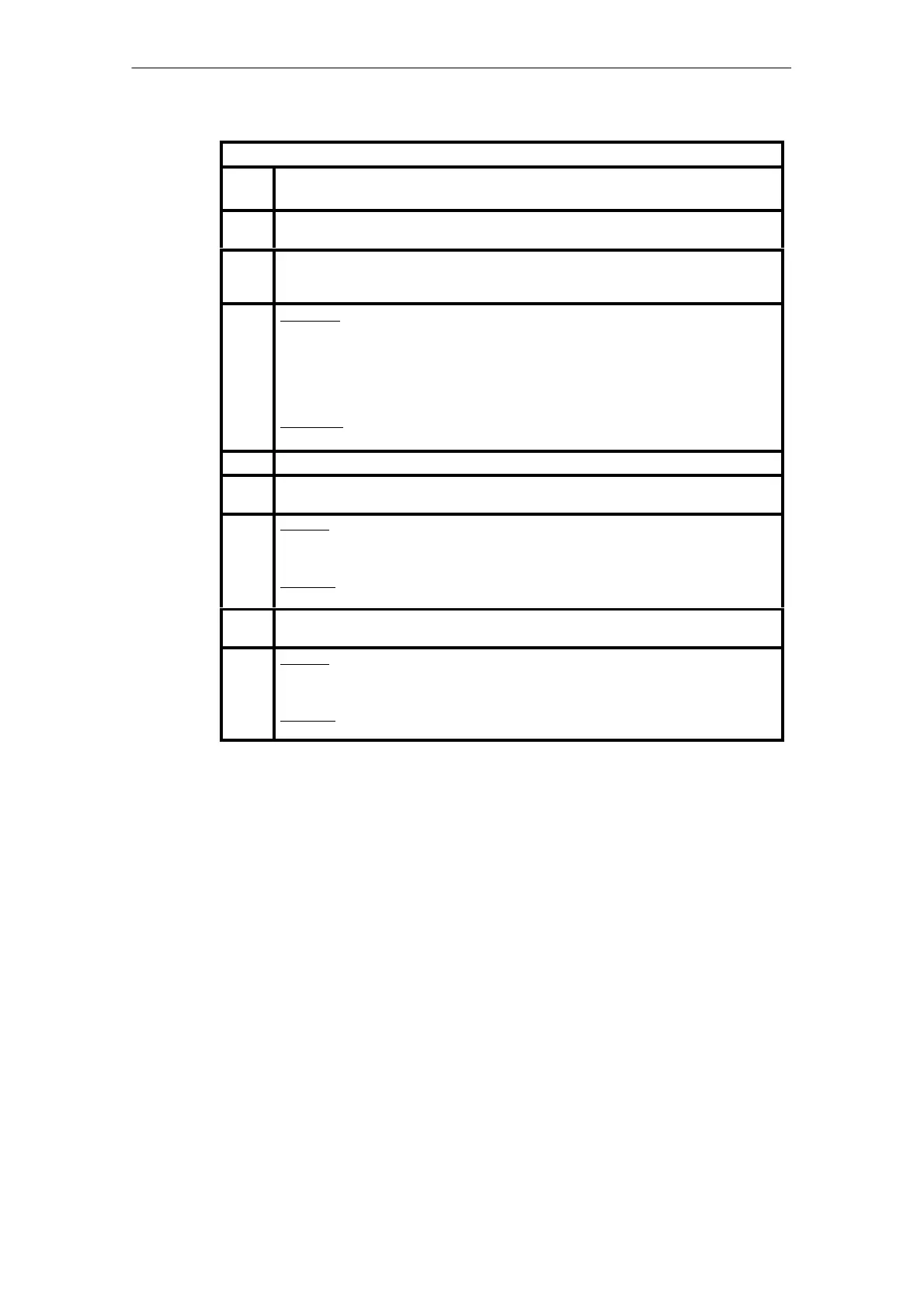
Information on the Output Telegram:
Word
No.
Meaning
1 Signal states at the usable binary output (DO) at the front connector X7A/ X7B.
Bit 15 corresponds to DO 16 (pin X719) – Bit 0 corresponds to DO 1 (pin X72)
2–9 Analog outputs AO 1 to AO 8
The analog values are transferred in fixed–point format. The representation corresponds to
the SIMATIC format. Measuring range, see below.
10
Low byte:
Bit 0 – 3: LZ Sign of life changing with the contents. Code: 0x05/0x0A or
0x03/0x0C.
Bit 4: RES Reserve bit
Bit 5: RPM Run Passive Master
Bit 6: MRV Master–state specification
Bit 7: ZRV Forced reserve specification
High byte:
Reserve
11 Reserve
12 –
43
In case of 6DL3100–8AB 32 words additional dynamic FEF signals
In case of 6DL3100–8AC it depends of configured FEF
44 Low byte:
Parameter block address 1 (only for 6DL3100–8AB)
Address of the parameter block (1 – 255). Address 0 is invalid.
High byte:
Reserve
45 –
60
16 words parameters (only for 6DL3100–8AB)
61 Low byte:
Parameter block address 2 (only for 6DL3100–8AB)
Repetition of parameter block address 1 as a backup measure.
High byte:
Reserve
Artisan Technology Group - Quality Instrumentation ... Guaranteed | (888) 88-SOURCE | www.artisantg.com
 Loading...


