Appendix
A.5 Acceptance Log
Control Units CU240S
Operating Instructions, 11/2006, A5E00766042B AA
A-13
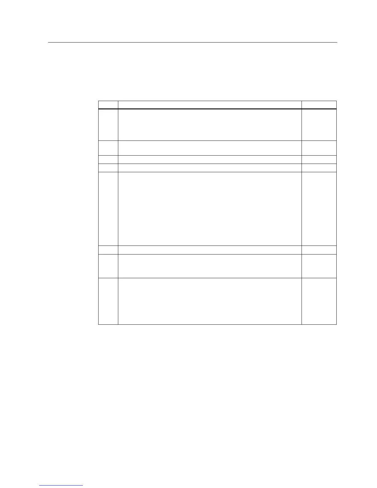
Function test "Safely-Limited Speed" (SLS)
This test comprises the following steps:
Table A-10 "Safely-Limited Speed" function (SLS)
No. Description Status
1. Initial state
• Drive in the "ready" state (P0010 = 0)
• No safety faults and alarms
• r9772.4 = r9772.5 = 0 (SLS de-selected and inactive)
2. Operate the drive (if the machine permits it, at a higher speed than the
parameterized safely-limited speed)
3. Check that the expected drive operates
4. Select SLS while issuing the traversing command
5. Check the following:
• r9772.4 = 1 (SLS selected)
• Drive speed decreases corresponding to the selected ramp time or SLS
mode (if required, use an oscilloscope)
• After the parameterized safely-limited speed has been fallen below, the
speed remains below this limit
– In SLS mode 1 à correct, must be no fault
– In SLS mode 0 à LSTO (safety fault at ramping end)
– In SLS mode 2 à LSTO (immediately)
• r9772.5 = 1 (SLS active)
6. De-select SLS
7. Check the following:
• No safety faults
• r9772.4 = r9772.5 = 0 (SLS de-selected and inactive)
8. Check that the expected drive operates if so the following is tested:
• The wiring between the control unit and power module is correct
• Correct assignment, drive No. – inverter power module – motor
• Correct functioning of the hardware
• Correct wiring of the shutdown paths
• Correct parameterization of the SLS function
 Loading...


