Communications configuring
System- and communication configuring D7-SYS - SIMADYN D 3-129
Edition 12.2003
(In this case, CS7 is called "D06CS7", communications module SS4 is
inserted at the 2nd connector).
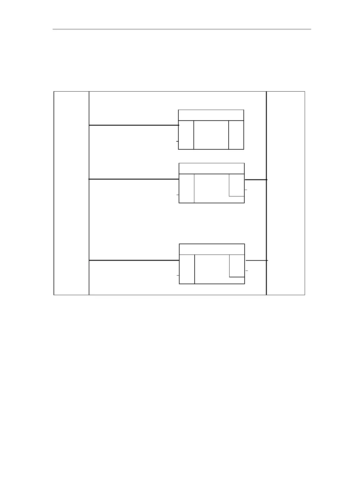
The data entries at inputs AT, AR of CTV/CRV must match those on
subrack 1, otherwise data will not be able to be transferred.
Righthand marginLefthand margin
ECL
ECO
CDM
QTS
-
-
-
-
-
-
-
CTS
BDR
TWU
CDV
@CSD01
CRT
QTS
YEV
CTV
-
-
-
-
-
CTS
T
MOD
EN
D06CS7.X02
'PZD1.100'
'H'
1
CRR
QTS
YEV
CRV
-
-
-
-
-
CTS
R
MOD
EN
!EMPF1
'PZD2.200'
'H'
1
19200
10
D06CS7.X02
!SND1
D06CS7.X02
Fig. 3-42 Configuring example: Subrack 1
3.8.4.2 Subrack 2
The DUST1 central coupling block as well as 1 transmit- and 1 receive
block are configured on CPU 3 of subrack 2. (in this case, CS7 is called
"D10CS7", communications module SS4 is inserted at connector X03).
Address stage 1 must be the same for blocks which communicate with
one another:
• Subrack 1, transmitter=subrack 2, receiver=100
• Subrack 1, receiver=subrack 2, transmitter=200
Description