Communications configuring
3-146 System- and communication configuring D7-SYS - SIMADYN D
Edition 12.2003
3.14 USS slave coupling
The USS slave coupling allows you to
− transfer process data
− handle and visualize parameters
To exchange process data, you have a maximum of
− one transmit channel (actual values) and
− one receive channel (setpoint).
You can transfer up to 32 process data sets, each 16 bits via each of
these channels.
For the coupling, you require a
T400 technology board (terminals 70..71,
serial interface X01 or terminals 74..75, serial interface X02)
.
Data transfer is realized using a half-duplex technique via a two-
conductor cable in accordance with the RS485 Standard.
• It is not possible to simultaneously use two USS couplings (USS
master, USS slave) at serial interfaces X01 and X02.
• You must switch-in switch S1/8 (close) so that you can use serial
interface X01
for the USS slave coupling.
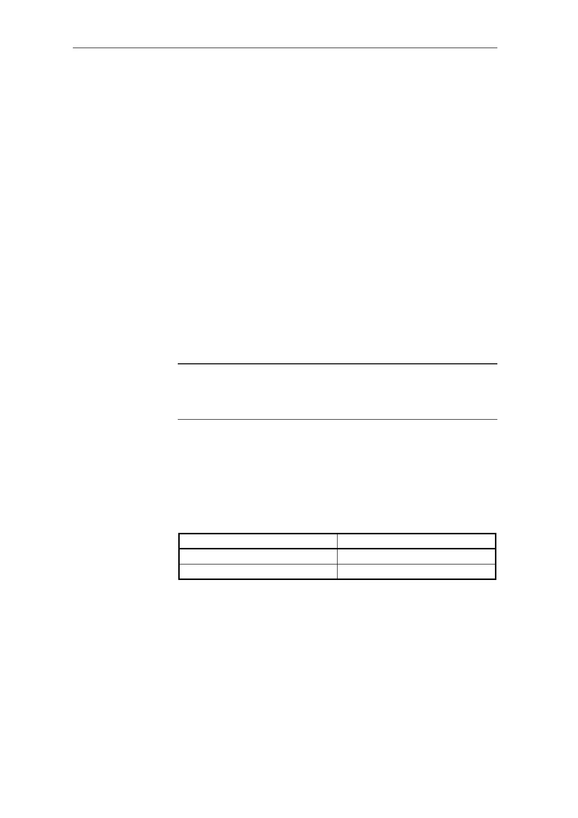
3.14.1 Basis network for the T400 technology module
Depending on whether you use the T400 technology board as end node
or
not as end node on the USS bus , i.e. at the end or not at the end of
the bus cable, then you must
open or close the switches according to the
table below
.
Serial interface Switches
X01 S1/1 and S1/2
X02 S1/3 and S1/4
3.14.2 Initialization
You must configure the function block @USS_S so that you can initialize
the USS slave bus coupling .
Please note the
following: