Closed-loop thyristor current control
System- and communication configuring D7-SYS - SIMADYN D 5-77
Edition 06.2002
5.8 Appendix
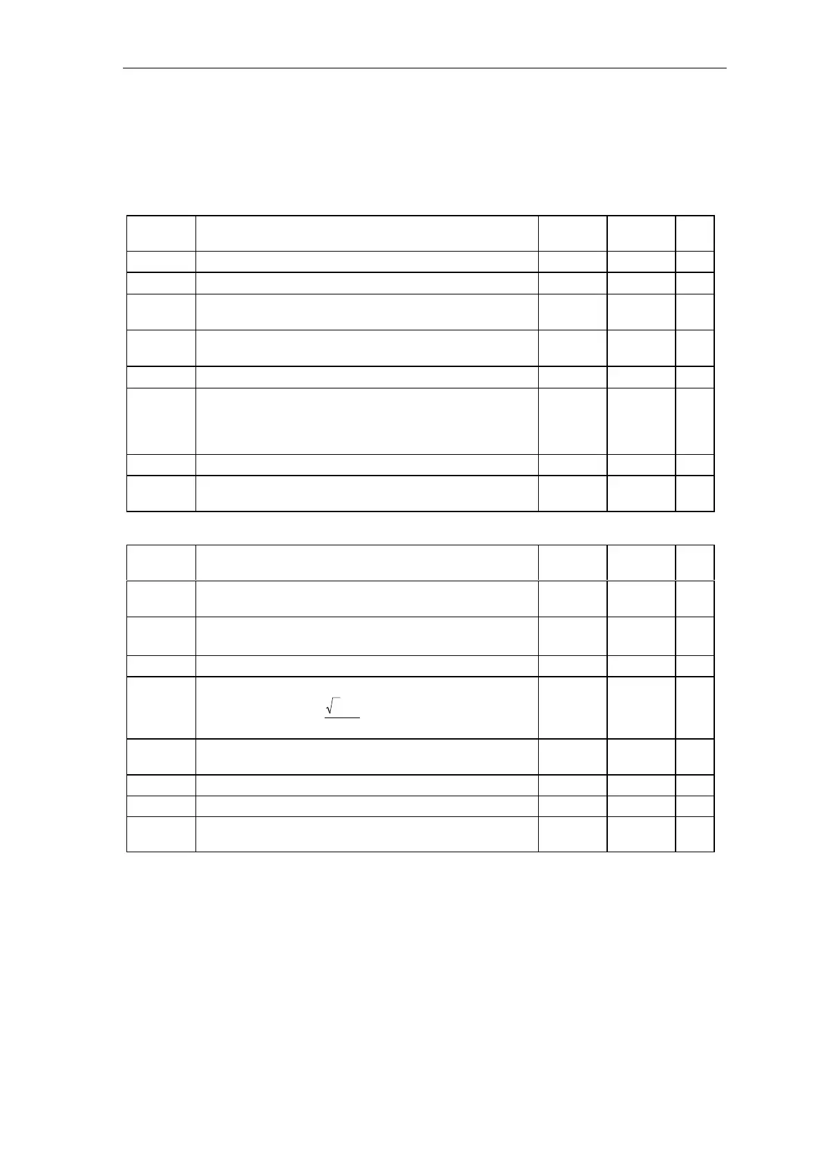
5.8.1 Standard configuration of parameters
Connec-
tion
Significance Value Value
change
Type
PA6.SYX
Mode: Source, synchronizing voltage 0 Init
PA6.XDA
Offset angle { -180°…+180° }
0.0
PA6.NAZ No. of failed line supply periods
Condition: 0
≤ NAZ ≤ 3050, > QSF\bit 9 = 1
8Init
PA6.NEP
No. of line supply periods
Condition: 0
≤ NEP ≤ 5000, > QSF\bit 9 = 1
5Init
PA6.NCM
Mode : Line supply handling { 0…4 , >4= 0 }
0
PA6.FAM
For NCM=1: Refer to 4
For NCM=2: Average value generation {
≥1…<8 }
For NCM=3: Decrease phase difference {
≥1…≤1000 }
For NCM=4: Decrease phase step {
≥1…≤1000 }
0
PA6.INV
Mode for rotating field detection 0 Init
PA6.FNT
Line frequency [Hz] for start of synchronization
Condition: 6
≤ FNT ≤ 600, > QSF\bit 9 = 1
50 Init
Connec-
tion
Significance Value Value
change
Type
EMF.RRV Rated Sitor voltage of the sensing [V].
Condition: RRV
≥ ARV, > QSF\bit 14 = 1
0.0 Init
EMF.ARV
Rated system / motor voltage [V]
Condition: RRV
≥ ARV
≠
0, > QSF\bit 14 = 1
0.0 Init
EMF.NF
Normalization of the voltage actual value at YUA 1.0 Init
EMF.AAV Line supply voltage [V].
Condition:
3
2
ARV AAV
π∗
⋅≥
, >QSF\bit 14 = 1
(0.0)
EMF.XFO
Offset frequency of the V/f converter [kHz]
Condition: -6 kHz
≤XFO≤ 6 kHz, > QSF\bit 14 = 1
0.0 Init
EMF.RA
Normalized armature resistance 0.0
EMF.TA
Armature time constant [ms] 0 ms
EMF.T
Smoothing time for YEV value
(the smoothing is switched-out with T=0)
20 ms