Communications configuring
System- and communication configuring D7-SYS - SIMADYN D 3-289
Edition 12.2003
Additional information
Refer to the Chapter "DUST1 coupling" and Chapter "MPI coupling" for
details on the DUST1 and MPI couplings.
3.25.1 Function block SER
"SER" function has a coupling connection. It can be configured several
times for each CPU.
The
CTS input designates the coupling module and the interface via
which an operator control device is connected.
A channel name and address stage 1 is specified at input
US.
• Channel name
− max. 6 characters
− ASCII characters with the exception of "point" and @
− the channel name on a data interface must be unique.
• Enter "." after the channel name
• Address stage 1
− CPU slot number. The operator control program addresses the
CPU via this number.
− The data entry must have two digits: e.g. "01", "02", ..., "24".
SER
-
--
-
CTS
US
LT
QTS
YTS
'CS7.X01'
'ser1.01'
240
1
st
CPU at slot 1
SER
-
--
-
CTS
US
LT
QTS
YTS
'
CS7.X01'
'ser2.04'
240
2
nd
CPU at slot 4
@CSD01
-
-
-
-
-
-
-
CTS
BDR
TWU
CDV
ECL
ECO
CDM
QTS
19200
240
'
CS7.X01'
0
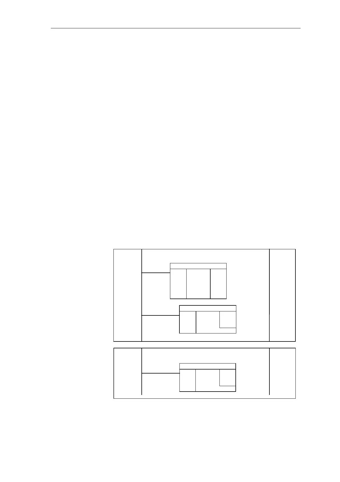
Fig. 3-115 Example: Configuring with CFC
Data entries at the
connections
Example:
Configuring with
CFC