Closed-loop thyristor current control
5-6 System- and communication configuring D7-SYS - SIMADYN D
Edition 06.2002
5.2 Function description
All of the converter-specific function blocks are described in this Section.
The system characteristic quantities are pre-assigned "0" (Default) for
example (e.g. rated voltages, rated currents and armature quantities).
All of the other parameters are pre-assigned non-critical values (e.g. low
controller gains, high integral action times).
A list of the parameters to be set is provided in Section 5.3.2.
The blocks have an initialization mode which is executed once after each
successful reset / restart. The values at several connections (Initialization
connections) are only read-in in the initialization mode;
changes at one of these initialization connections (Init) are therefore only
effective after a reset
Each function block checks the entries for plausibility when specific
quantities are configured and when conflicts arise, it outputs a fault ID at
fault word QSF.
All of the fault words are collected in the switch-over logic stage FB SOL
and are evaluated. The closed-loop thyristor current control cannot be
switched-in if there is a configuring error (refer to Section “SOL, switch-
over logic stage”).
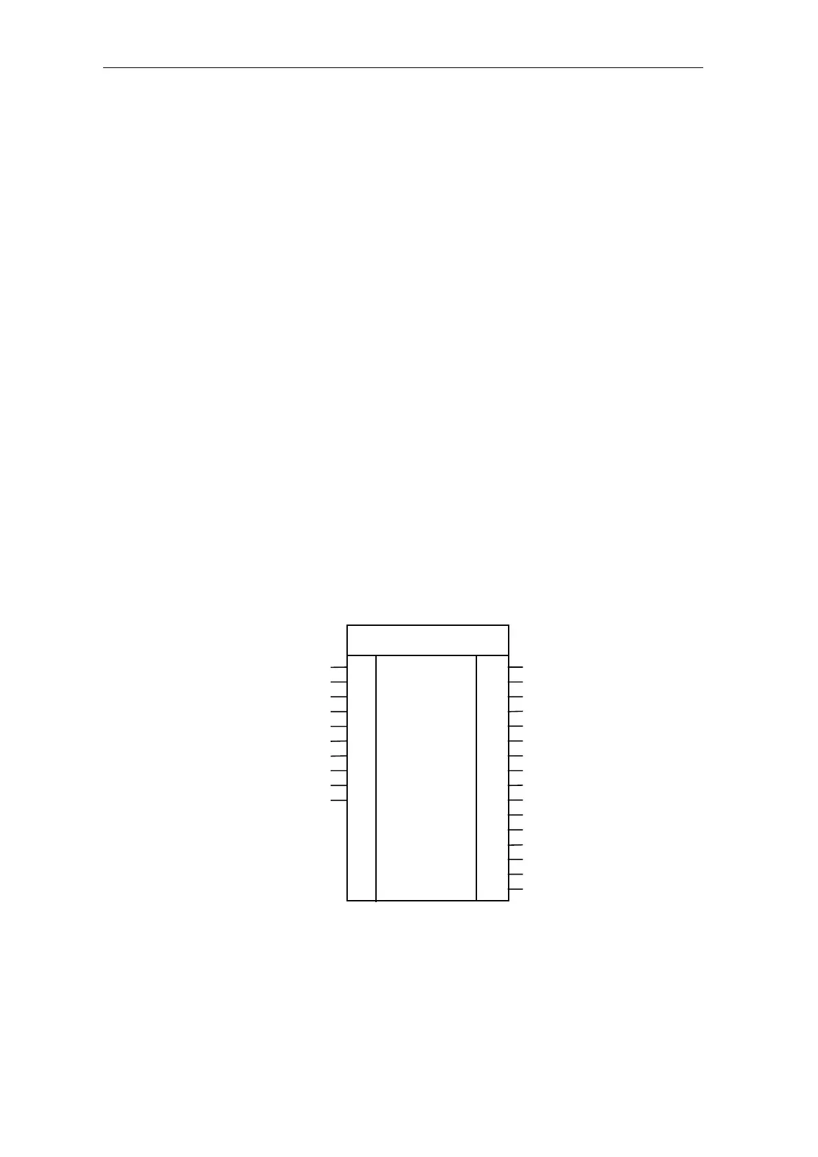
5.2.1 PA6, synchronization
Hardware address
Mode:V syn ,int./ext. synchr.voltage
Firing pulse numbe
Offset angle line/synchr.voltage
#Failure line periods up to signal
#Stabilizing line periods
Mode:Line handling
#Line periods, average
Mode:Rot. field identification
Line frequency [Hz]
GV
BO
I
R
DI
DI
I
I
I
R
D
SYX
ZPA
XDA
NAZ
NEP
NCM
FAM
INV
FNT
PA6
CTH
CTS
RDY
Y6R
XAS
NZG
TA
AFP
AFI
AVW
YIT
YDA
XFN
ZYA
ZDA
QSF
DI
DI
BO
DI
R
DI
TS
R
R
R
R
R
R
I
I
W
Time value, firing pulse output
Time value, PA6 start
Line is ok, enable PC6
60° value of the line periods [16 MHz]
Firing angle actual value [ASG]
360° value of the line periods [16 MHz]
Time diff. line interrupt [ms]
Firing angle, act. value [
°
]
Line filter, phase shift [
°
]
Offset ang. comp. in firing angle act. val.
Current duration in the gaps
Measured offset angle
Measured line frequency
Diag.:Synchr. state machine
Diag.:Rot. field state machine
Fault
Fig. 5-3 PA6 represented in the CFC
Parameter defaults
Init connections
Configuring errors