Communications configuring
System- and communication configuring D7-SYS - SIMADYN D 3-139
Edition 12.2003
390
390
150
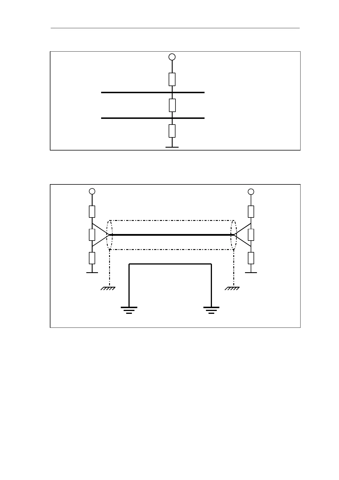
RS485+
RS485-
Bus terminating resistor
+5V
0V
Resistor to the
su
l
volta
e
Resistor to the
si
nal reference
Fig. 3-44 Basis network and bus termination
390
Ω
390
Ω
150
Ω
390
Ω
390
Ω
150
Ω
Housing ground,
grounding bar
The screen should
be
connected to the grounding bar
through the largest possible
surface area where the
cable enters the cabinet
Screen
Data line
Potential bonding
Housing ground,
grounding bar
The screen should be
connected to the grounding bar
through the largest possible
surface area where the cable
enters the cabinet.
Fig. 3-45 Screening and potential bonding
This circuit should be used if the SS4 communications module is used as
end node on the USS bus, i. e. at the end of the bus cable.
Connector
assignment with
basis network