Closed-loop thyristor current control
5-66 System- and communication configuring D7-SYS - SIMADYN D
Edition 06.2002
More detailed information about the assignment of the interfaces
specified above is provided in the "Hardware" Manual in the Section "
ITDC expansion module".
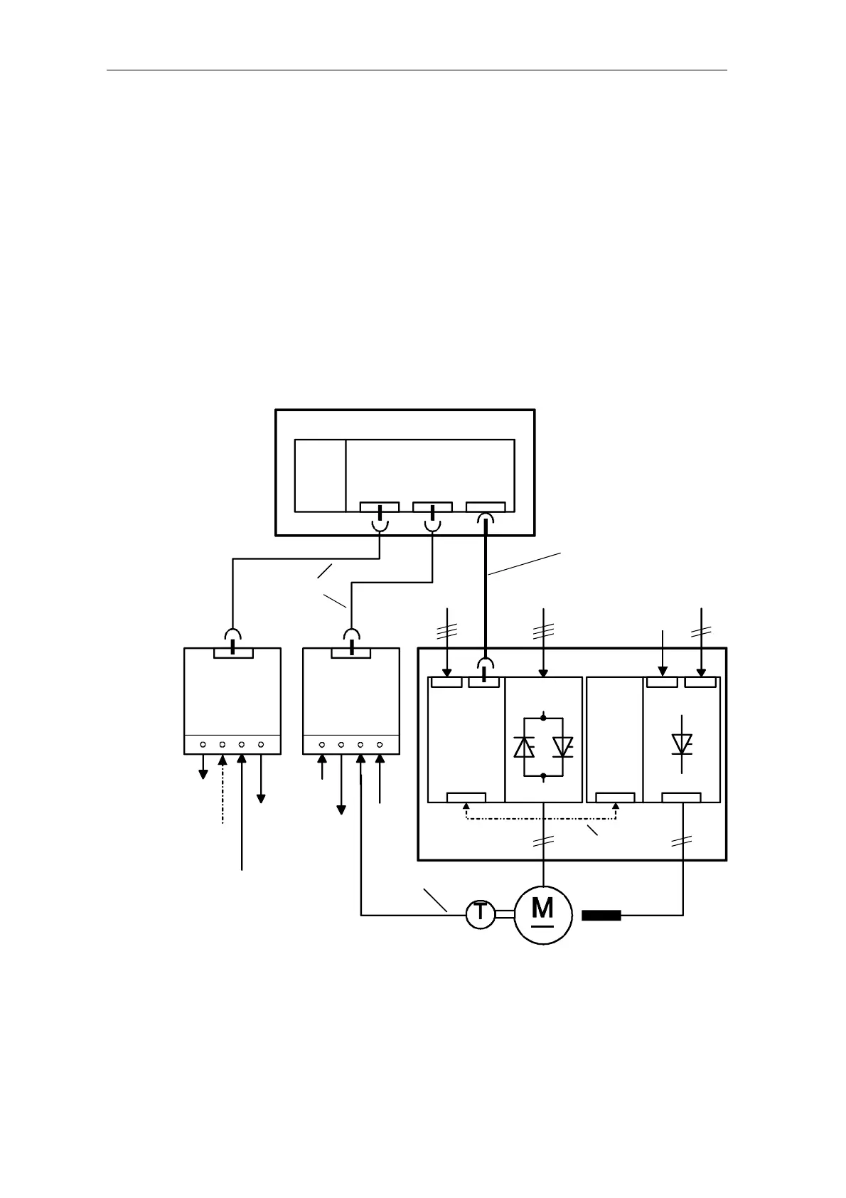
A clockwise rotating field with the same phase sequence must be
connected at the power connections and the power supply for the
electronics module -A1. The zero crossovers of voltages V
L12
and V
L13
are retrieved from the power section supply.
The synchronizing voltage is taken from the electronics section at the
secondary of the supply transformer.
If the synchronizing voltage from the SITOR set cannot be used, for
example because the power supply of the SITOR set electronics does not
have the same phase sequence as the power connections, then an
external synchronizing voltage can be entered via connector ITDC-X5:
5/6 ( 15[V
RMS
] , range 10-20[V
RMS
], internal resistance 20[kΩ] )
SIMADYN D rack SRx
PM
5/6
ITDC
X1 X2
X11
X100
L1/L2/L3
SITOR set
6QG3x
AK1 /3 /5
X5
X6 X7
power sect.
X103
Field
device
-A2
(option)
electronics
module
-A1
interface mod.
SU11
interface mod.
SU11
SC12
20 core
X1X1
X2 X2
1AO
Ext.
V
SYN
Ext.
pulse inhibit
Diagnostic
signals
4DI
4DO
X102
Enable
X103
AM/KM
10 core
24V
SC17.2 (2 m)
or
SC31.2 (10 m)
50 pin
L1/L2/L3 L1/L3
1 incremental
encoder
for DO
Fig. 5-36 Connection diagram SIMADYN D – SITOR set