Systemsoftware
2-48 System- and communication configuring D7-SYS - SIMADYN D
Edition 03.2001
The acknowledge button of the CPU module or the possibility of
acknowledging via the service interface is provided as external input of
the system chart. The 7-segment display of the CPU module or the
diagnostics LED (T400) are available as external outputs for the user
display.
The two connections SIMS.QS and SIMD.Q can be evaluated to handle
an error in the user program. The error outputs of the individual
components are combined to form an error status word via the SIMS
function block. The SIMD.Q output connection represents a general error
status.
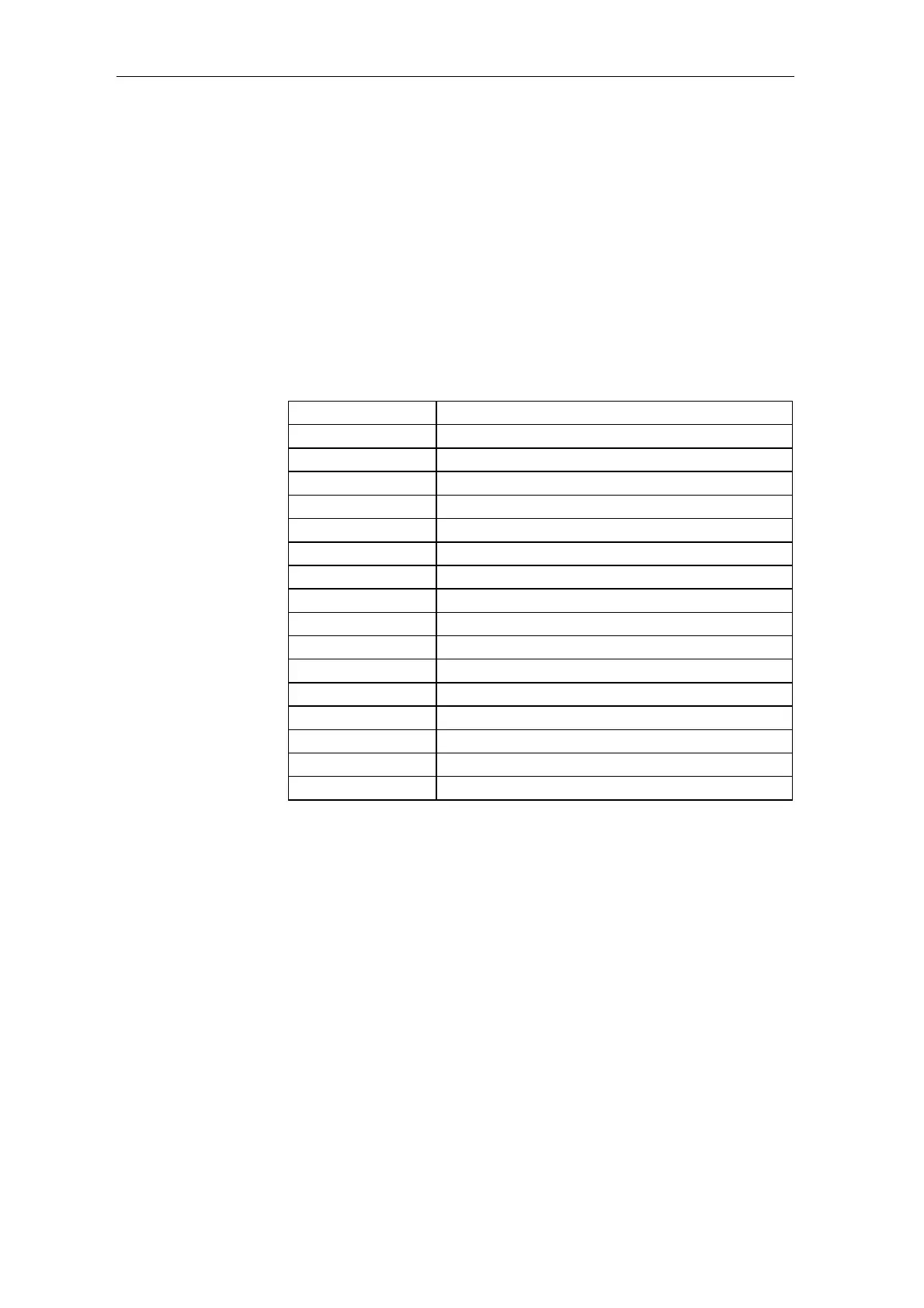
The error status word at the SIMS.QS block connection has the following
bit assignment:
Bit Bit assignment
Bit1 Unused
Bit2 Unused
Bit3 Unused
Bit4 Task administrator error
Bit5 Unused
Bit6 Hardware failure
Bit7 Communications error
Bit8 Unused
Bit9 Unused
Bit10 Unused
Bit11 User-generated error ID
Bit12 Unused
Bit13 Unused
Bit14 Unused
Bit15 Unused
Bit16 Unused
Table 2-16 Bit assignment of the function block connection SIMS.QS
Interfaces