Description
3.2 Design
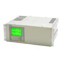
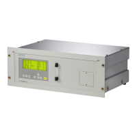
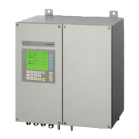
FIDAMAT 6
Operating Instructions, 01/2019, A5E00222135-04
21
The FIDAMAT 6E –Y27 is preconfigured for this and expects an analog signal of 4 ... 20 mA
corresponding to 0 ... 21 vol% O
2
at analog input AI2.
Additional application according to 17th BImSchV
This function pertains only to device version 7MB2421-xDA1x-1AAx–Y37 for the CEM Cert
system set "Fidamat 6 Measuring System II".
The device has an internal oxygen compensation. No external oxygen connection is
permitted for this application. Oxygen-free gases are to be used for calibration of zero gas
(function 20) and calibration gas (function 21).
3.2 Design
3.2.1 Design of the device
Overview
The FIDAMAT 6 is made up of two main assemblies:
● Electronics
● Analyzer part
The FIDAMAT 6 is designed in such a way that the parts contained in it are easy to access
for service. Access from both the top (for maintenance of individual components) and the
rear is possible. The gas connections and the electrical connections are located on the back
of the device.
The sample gas pump of the FIDAMAT 6-E is easily accessible from the top.
Electronics
The electronics consists of:
● Control board with display
The control board is integrated into the front panel
● Motherboard
● Adapter board
The adapter board contains the preamplifier for the measured value acquisition and the
control unit.
● Option boards: PROFIBUS (DP/PA), AUTOCAL

 Loading...