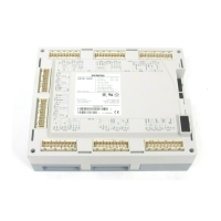
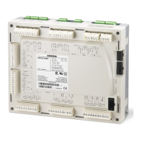
LMVSeries
TechnicalInstructions
LV5‐1000
Parameter ProgramStop
PS PS PS PS PS PS PS
Oil Train :
HO w Gasp
Lockout Phase
Safety Phase
Home Run Position
Burner Standby
Safety Relay = ON
Release of Startup,
SV = ON
Combustion Fan = ON
Drive to Prepurge Pos.
Prepurge
Prepurge (Aux 3 Drive t
Prepurge Pos.)
Prepurge 2 (Aux 3 FGR)
Drive to Ignition Pos.
Preignition (Spark) = ON
Pilot Valve = ON
Ignition (Spark) = OFF
Interval 1
(Pilot Stabilization)
Safety Time 2
Interval 2
(Main Stabilization)
Drive to Low Fire Pos.
Operation 1
(Normal Operation)
Operation 2
(Driving to Low Fire)
Afterburn Time
Driving to Postpurge
Position
Optional Postpurge 3
Direct Start
Phase 00 01 10 12 20 21 22 24 30 32 34 36 38 40 42 44 50 52 54 60 62 70 72 74 76 78 79
Terminal Description Notes
X4-01.2
Fuel Select Oil Note 1
M
X3-04.1
Safety Loop (Limits)
N/
Internal Temperature Limit
X5-03.1
ON / OFF Switch Note 2
N/
Flame Signal Note 9
XM F
X3-02.1
Blower Air SW (APS) Note 8
F
M
Blower Aux. Contact (FCC)
M
FGR Press. SW (instead of FCC) Note 15
M
POC SW Gas (CPI)
POC SW Oil (CPI)
F
M
POC SW Gas + Oil (CPI)
F
M
X9-03.4
Low Gas Press SW Note 5
M
POC SW Gas (CPI)
POC SW Oil (CPI)
F
M
POC SW Gas + Oil (CPI)
F
M
Start Rel. Oil (Atom. Media PS)
M
Ext. Flame SG Red. Contact Note 9
F
M
Heavy Oil Direct Start Note 16
External Flame Safeguard Note 9
XM F
X5-02.2
High Oil Press SW
M
Low Oil Press SW (activated)
M
Low Oil Press SW (act from ts)
M
X3-01.1
Fan Note 12
X4-02.3
Ignition
X
X6-02.3
Oil Pump Motor Starter Note 6
X
Start Signal
X
3 Way Valve (APS checking) Note 10
X
XX
3 Way Valve (APS checking) INV. Note 10
X3-01.2
Alarm Note 3
XX
X6-03.3
Oil Valve SV (or Atom. Media)
X
X9-01.1
Gas Valve SV (Usually Outdoor)
X
X9-01.2
Gas Valve PV (Pilot Valve) Note 4
X
X
X8-01.2
Main Fuel Indicator (Oil)
X
XX
X8-02.1
Oil Valve V1 (Main)
X
XX
X8-03.1
Oil Valve V1 (Main)
X
XX
X7-01.3
Oil Valve V2
X
XX
X7-02.3
Oil Valve V3 (Staged, load depen.)
X
XX
Legend : Energized
M
Must be Energized by end of Phase See the first pages of
Energized or De-energized
F
Must be De-energized by end of Phase Section 3-3 for notes.
De-energized
X7-03.2
See Note 6
X5-01.2
Mandatory
Postpurge 1
START-UP
See Note 16
X6-01.3
X6-01.1
INPUTS
OPER-
ATION SHUTDOWN
OUTPUTS
PURGE
SAFETY
TIME 1
X4-01.3
X9-03.2
X4-03.3
See Note 12
SCCInc. Page56 Section3

 Loading...


