LMVSeries
TechnicalInstructions
LV5‐1000
ParameterProgramStop
PS PS PS PS PS PS PS
Actuators
Lockout Phase
Safety Phase
Home Run Pos.
Burner Standby
Safety Relay = ON
Release of startup,
Safet
Valve = ON
Comb. Fan = ON
Drive to Purge Pos.
Prepurge 2 (FGR)
Drive to Ignition Pos.
Preignition (Spark) = ON
Pilot Valve = ON
Ign. (Spark)= OFF
Interval 1 (Pilot
Stabilization)
Safety Time 2
Interval 2 (Main
Stabilization
Drive to Low Fire Pos.
Operation 1 (Norm.
O
eration
Operation 2 (Driving to L.
Fire
Afterburn Time
Driving to Postpurge Pos.
Optional Postpurge 3
Direct Start
Evacuate
Atmospheric Test
Fill
Pressure Test
Phase
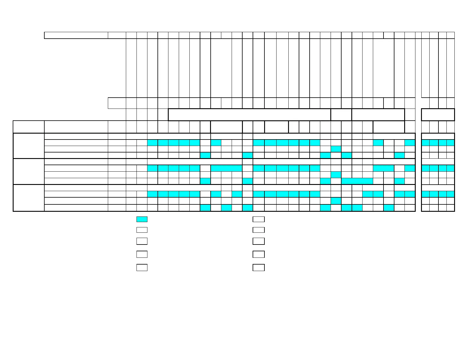
00 01 10 12 20 21 22 24 30 32 34 36 38 40 42 44 50 52 54 60 62 70 72 74 76 78 79 80 81 82 83
Actuator Description Notes
Expected Position Note 7
TT TMTST
Position Required to Proceed Note 13
Dynamic Position Checking Note 13
Run-Time Position Checking Note 13
Expected Position Note 7
TTMTST
Position Required to Proceed Note 13
Dynamic Position Checking Note 13
Run-Time Position Checking Note 13
Expected Position Note 7
T PrP T T M T S T
Position Required to Proceed Note 13
Dynamic Position Checking Note 13
Run-Time Position Checking Note 13
Legend :
os
t
on c
ec
e
y state
met
o
PrP
repurge pos
t
on
ee t
e
rst pages o
ect
on
-
or notes.
os
t
on not c
ec
e
I
gn
t
on pos
t
on
U
Undefined position
M
Actuators modulating
H
Home position
S
Actuators stopped
T
Actuators transitioning
PsP
Postpurge position
See Note 7PsP
I PsP
H
See Note 7H
Aux 3
UIH
Gas / Oil or
Oil
U
Air, Aux 1,
Aux 2, VSD
OPER-
ATION SHUTDOWN
GAS VALVE
PROVING
See Note 7
Mandatory Postpurge 1
I PsP
POST-
PURGE
Prepurge
H PrPU
START-UP
PRE-
PURGE
SAFETY
TIME 1
SCCInc. Page57 Section3

 Loading...

