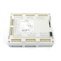
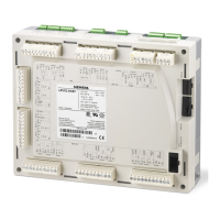
LMVSeriesTechnicalInstructions
DocumentNo.LV5‐1000
SCCInc. Page3 Section7
CANbusFaultsIncluding“AZLnotonBus”and“SystemTest”(continued)
ThemostcommonCANbuserrorsare:
“AZLnotonBus”
Stuckin“SystemTest”
Errorcode99
ErrorcodeA7,diagnostic17
However,therearemanyadditionalerrorcodesthatcanalsobecausedbyanissuewiththe
CANbusnetwork.ThefollowingprocedurecanbeusedtodiagnoseanyCANbusrelatederror:
1. Takethecoveroffofthelastactuator(orPLL52O
2
module)ontheCANbusnetworkwired
toterminalX51ontheLMV5.Thisshouldhaveonlyone5‐pingreenconnectorpluggedinto
it.TheotherCANbusterminalsshouldbeempty,andisaperfectplacetomeasurevoltage.
EnsurethatthefollowingvoltagesarepresentonthepinsoftheemptyCANbusterminal:
12VACbetweenpins12VAC1andGND
12VACbetweenpins12VAC2andGND
24VACbetweenpins12VAC1and12VAC2
Whenmeasuringtoground(GND),itisoktohaveanywherefrom10.2‐13.2VACaslongas
bothmeasurementsarethesame.Forexample,itisokaytohave11VACbetweenpins
12VAC1andGNDaslongasthereisalso11VACbetweenpins12VAC2andGND.In
addition,thevoltagebetweenpins12VAC1and12VAC2mustbeexactlydoubletheother
twomeasurements.Ifthesethreevoltagemeasurementsarecorrect,skiptostep3.
2. Ifoneormoreofthevoltagemeasurementsisincorrect,checkthefollowing:
CANbusfusesFU2andFU3arelocatedontherighthandsideoftheLMV5.Check
thatthesefusesarenotblown.Ifeitheroneisblown,checktheLMV5wiringfor
incorrectterminations.Onceanywiringerrorshavebeenfixed,replacetheblown
fuse.
Themostcommonwiringerrorhastodowithpins3and4ontransformerterminal
SEK2.Pin3onterminalSEK2shouldbewiredtoterminalX52,pin4ontheLMV5.
Pin4onterminalSEK2shouldbewiredtoterminalX52,pin3ontheLMV5.
Makesurepin3onterminalSEK2ofthe transformerisgroundedproperly.
MakesuretherestoftheCANbusnetworkiswiredproperly.SeeSection2for
additionalwiringassistance.

 Loading...


