Device Display Meaning for the LMV5x System Corrective Action
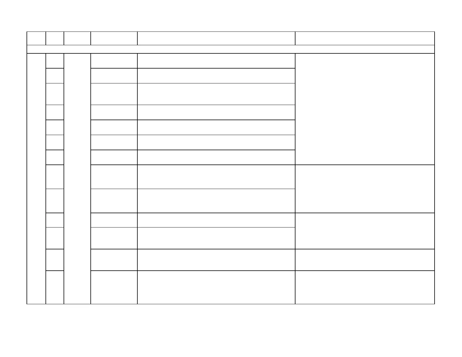
50
Short-circuit
Pt100 Sensor
Short-circuit sensor PT100, terminals X60.1, X60.4
51
Open-circuit
Pt100 Sensor
Open-circuit sensor PT100, terminals X60.1, X60.4
52
Open-circuit Pt
100 Sensor (Line
Compens)
Open-circuit compensation line of sensor PT100, terminals
X60.2, X60.4
53
Short-circuit
Pt1000 Sensor
Short-circuit sensor PT1000, terminals X60.3, X60.4
54
Open-circuit
Pt1000 Sensor
Open-circuit sensor PT1000, terminals X60.3, X60.4
55
Short-circuit
Ni1000 Sensor
Short-circuit sensor Ni1000, terminals X60.3, X60.4
56
Open-circuit
Ni1000 Sensor
Open-circuit sensor Ni1000, terminals X60.3, X60.4
57
Overvoltage at
Input 2
Overvoltage at input 2, terminal X61
58
Open-circuit /
Short-circuit
at Input 2
Open-circuit / short-circuit input 2, terminal X61
59
Overvoltage at
Input 3
Overvoltage at input 3, terminal X62
5A
Open-circuit /
Short-circuit
at Input 3
Open-circuit / short-circuit input 3, terminal X62
5B
Output Value for
available
Selected output value for analog output is not available in the
current configuration
Ensure parameter OutValueSelection is a valid
selection based on the devices connected to the basic
unit.
5C
use (LC, FGR, or
temp. of the
combustion air)
An invalid selection was made concerning the configuration of
a temperature sensor.
Ensure the following five temperature sensor
configuration parameters have valid selections based
on the devices connected to the basic unit: Sensor
Select , FGR-sensor , SupAirTempSens ,
1) Check signals wired to X62. Check wiring. Check
parameter Ext Inp X62 U/I . Re-wire if necessary.
Fault with Sensors Connected to Internal Load Controller, in Base Unit (LMV5)
A6
LMV5
Load
Module
1) Check pressure sensors wired to X61. Check wiring
and sensor. Check parameters Sensor Select and Ext
Inp X61 U/I . Re-wire or replace sensors if necessary.
2) If using a 4-20 mA pressure sensor, this fault occurs
when the boiler pulls a vacuum. Replace with a 0-10
Vdc sensor, or a higher range 4-20mA sensor.
Check temperature sensors connected to X60
terminals. Check wiring and sensor. Check parameter
Sensor Select. Re-wire or replace sensors if
necessary.
Section 7 Page 45 SCC Inc.
 Loading...

