Home
Siemens
Control Systems
MCP 398C
Siemens MCP 398C Commissioning Manual
4
of 1
of 1 rating
1734 pages
Give review
Manual
Specs
To Next Page
To Next Page
To Previous Page
To Previous Page
Loading...
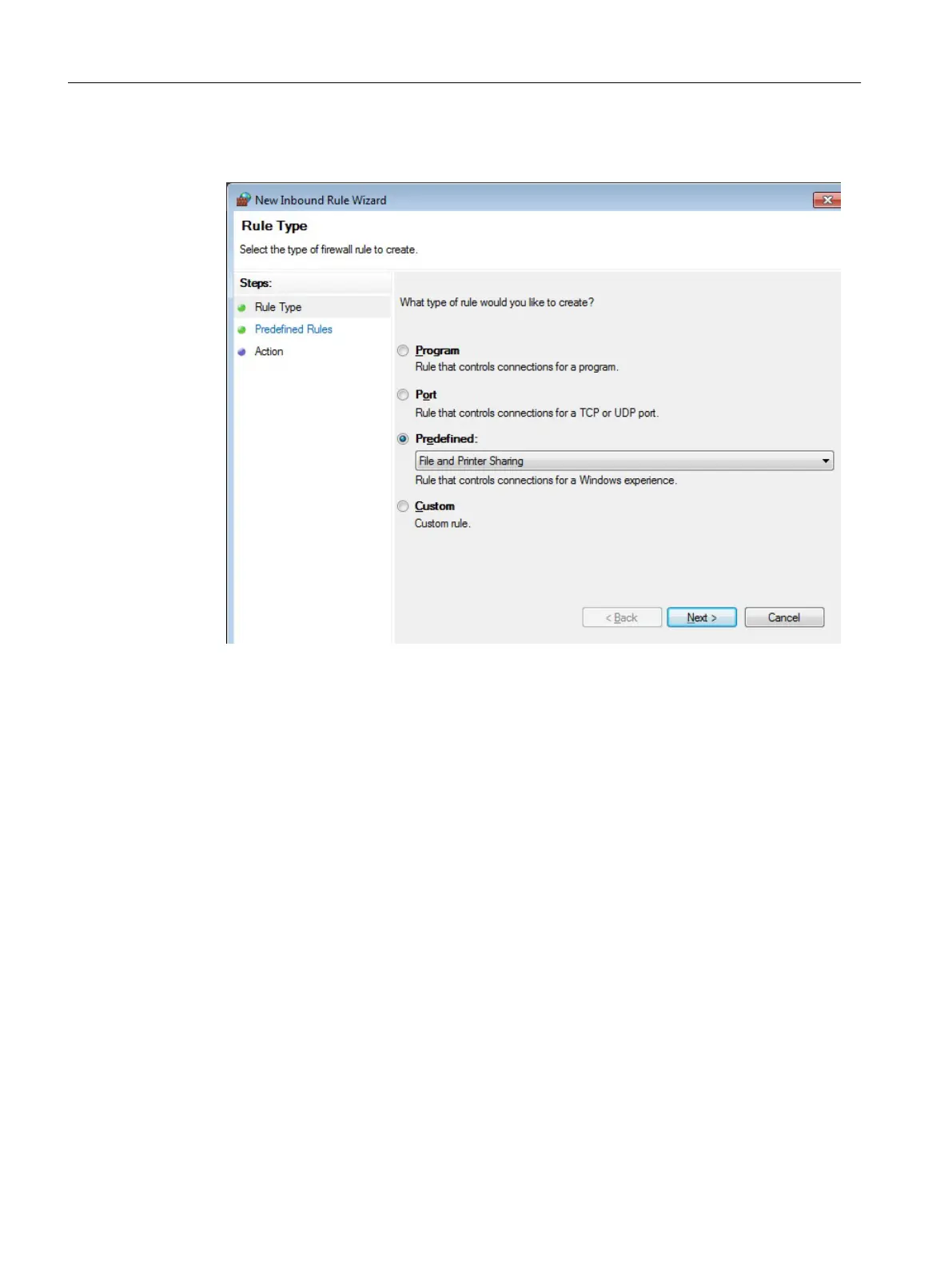
5.
In the "New Inbound Rule Wizard" dialog, select the option button "Predefined", select in
the "File and Printer Sharing" drop-down list, and click on "Next".
Configuration of the system
4.17 Adapting the firewall settings
PCU Base Software (IM10)
82
Commissioning Manual, 12/2017, 6FC5397-1DP40-6BA1
1639
1641
Table of Contents
Basesoftware and operating software
1
Legal information - Warning notice system
2
Preface
3
Table of contents
5
1 Fundamental safety instructions
7
1.1 General safety instructions
7
1.2 Equipment damage due to electric fields or electrostatic discharge
11
1.3 Warranty and liability for application examples
12
1.4 Industrial security
13
1.5 Residual risks of power drive systems
14
2 SINUMERIK Operate (IM9)
15
Legal information - Warning notice system
18
Table of contents
19
1 System overview
31
1.1 System overview
31
1.2 System requirements
32
2 Principles of start-up
35
2.1 Data structure of SINUMERIK Operate
35
2.2 Editing files
38
2.2.1 Editing the file at the controller
38
2.2.2 Editing a file externally
40
3 General settings
43
3.1 Changing the language
43
3.2 Set date/time
44
3.3 Using the time server
46
3.4 Use time zone
47
3.5 Configuring Caps Lock
48
3.6 Activating/deactivating the virtual keyboard
49
3.7 Defining the access rights for the "HMI restart" softkey
49
3.8 Changing the skin design
50
3.9 Setting the screensaver
50
3.10 Inserting a user-specific run up screen
51
3.11 Access levels
51
3.11.1 Definition of access levels
51
3.11.2 Modifying the access levels password
52
3.11.3 Access levels for programs
54
3.11.4 Access rights for files
56
3.11.5 Access levels for softkeys
57
3.11.6 This is how you define new access levels for softkeys
58
3.12 Program selection
60
3.12.1 Displaying the softkey
60
3.13 Activate and configure the Sidescreen window
62
3.13.1 Activate Sidescreen
62
3.13.2 Display Sidescreen ABC keyboard
63
3.13.3 Display Sidescreen machine control panel
64
3.13.3.1 Configuring your own keys on the machine control panel
65
3.13.3.2 Create own translations of texts for the machine control panel
67
3.14 Display Manager
68
3.14.1 Display configurations
68
3.14.2 Creating your own display configurations
69
3.14.2.1 Displays
69
3.14.2.2 Frames
70
3.14.2.3 Menus
72
3.14.2.4 Menu actions
78
3.14.2.5 Applications
80
3.14.2.6 Global settings
84
4 Licensing
87
4.1 Determining the license requirement
88
4.2 Activating the test license
90
4.3 Exporting license requirements
91
4.4 Reading in the license key
91
4.5 Backing up the license of a new CompactFlash card.
92
5 Creating drive connections
95
5.1 Setting up drives
95
5.2 Setting EXTCALL
96
5.3 Setting the EES
96
5.4 Creating a global part program memory
97
6 Channel menu
99
6.1 Configuring a channel menu
99
6.2 Constraints
100
6.3 General structure of the channel menu
100
6.4 Defining channel groups in the "netnames.ini" file
101
6.5 Configuring operating stations in the "config.ini" file
102
6.6 Example: Settings for 1:N
103
6.7 Distribution via job lists in the case of 1:N
105
7 Machine and setting data
109
7.1 Machine and setting data
109
7.2 Displaying/editing machine data
109
7.3 Displaying/editing display machine data
112
7.4 Displaying/editing setting data
112
7.5 Displaying/editing drive parameters
114
7.6 Machine data display options
116
7.7 Editing machine data and drive parameters
118
7.7.1 Editing hexadecimal values
118
7.7.2 Editing BICO values
119
7.7.3 Editing enum values
119
7.8 Searching for data
120
7.9 Managing data
122
7.10 User views
124
7.10.1 Creating a user view
125
7.10.2 Editing the user view
126
7.10.3 Deleting a user view
128
7.11 Plain texts for machine and setting data
128
8 Customizing the "Machine" operating area
131
8.1 Setting the font size of the actual value display
131
8.2 Inserting a user-specific logo
131
8.3 Configuring the display of the G-code groups
133
8.4 Configuring the channel operational message
134
8.5 Deactivating program test
136
8.6 Display STAT and TU
137
8.7 Activating the "Teach In" function
137
8.8 Block search
139
8.8.1 Activating block search mode
139
8.8.2 Accelerated block search for execution from external
141
8.9 Multi-channel support
141
8.10 Manual machine
143
8.11 User status display (OEM)
145
8.12 Configuring the offset display
148
8.13 Activate machining time recording
148
9 Simulation and simultaneous recording
151
9.1 Simulation overview
151
9.2 Setting the technology for simulation
153
9.3 Simultaneous recording overview
155
9.4 Clamping a blank
156
10 Spindle functions
161
10.1 Spindle control
161
10.2 Analog spindle
162
10.3 Spindle diagnostics
163
10.3.1 Spindle diagnostics
163
10.3.2 Temperatures
165
10.3.3 Motor temperature sensor
167
10.3.4 Additional temperature sensor
167
10.3.5 Temperature histograms
168
10.3.6 Speed/torque
168
10.3.7 Clamping system
169
10.3.8 Clamping system: Speed limits
171
10.3.9 Clamping system: Diagnostic statistics
172
10.3.10 Clamping system: Clamping time statistics
173
10.3.11 Fetching the logistics data
173
11 Drive system
175
11.1 Commissioning of drives
175
12 Tool management
177
12.1 Machine data for tool management
177
12.1.1 Settings with/without magazine management
177
12.1.2 Configuring the access levels of the tool management
178
12.1.3 Additional settings
180
12.2 Configuring the user interface
183
12.2.1 General settings
186
12.2.2 Configuring tool lists
191
12.2.2.1 Tool parameter identifiers
195
12.2.2.2 Cutting edge parameter identifiers
197
12.2.2.3 Monitoring parameter identifiers
200
12.2.2.4 Grinding parameter identifiers
201
12.2.2.5 Magazine location parameter identifiers
202
12.2.2.6 Magazine location adapter parameter identifiers
203
12.2.2.7 Multitool parameter identifiers
203
12.2.2.8 Multitool location parameter identifiers
204
12.2.3 Configuring list parameters
205
12.2.4 List of tool types
209
12.2.5 Configure tool types
211
12.2.6 Configuring the "Additional Data" window
213
12.2.7 Configure the "New tool - favorites" window
215
12.2.8 Configuring the "New Tool" window
216
12.2.9 Configuring the "New Multitool" window
216
12.2.10 Configuring the "New Tool from Code Carrier" window
217
12.2.11 Configuring the "New Tool from File" window
217
12.2.12 Configuring default values for new tools
218
12.2.13 Configuring the "Details" window
222
12.2.14 Assigning a name for magazines and magazine locations
222
12.2.15 Configuring the "Assign Tooltips for Multitool Locations" window
224
12.2.16 Assigning a name for magazine location types
225
12.2.17 Assignment of magazines and magazine locations to channels
226
12.2.18 Assignment between magazines and magazine locations and coordinate systems
228
12.2.19 Disabling the softkey depending on filters
229
12.2.20 Configuring the "Load Station Selection" window
230
12.2.21 Coolant and tool-specific functions
231
12.2.22 Reason for the tool change when reactivating
234
12.2.23 Configure the code carrier connection
238
12.2.24 Configuring Save to file
241
12.3 Creating OEM texts
242
12.3.1 Identifiers of the standard texts
243
12.3.2 Examples of OEM texts
246
12.4 Examples
248
12.4.1 Example: Configuring an OEM tool list
248
12.4.1.1 Adapting the configuration file
248
12.4.1.2 Adaptation of the customer text file
250
12.4.2 Example: Configuring magazine location types with names
252
12.4.2.1 Adapting the configuration file
252
12.4.2.2 Adaptation of the customer text file
253
12.5 Working with two tool holders
256
12.6 Editor for the tool and magazine management
258
12.6.1 Function overview of the tool management editor
258
12.6.2 Editing the tool management
259
12.6.3 Parameterizing the tool management
262
12.6.3.1 Create tool unit
262
12.6.3.2 Define buffer locations
263
12.6.3.3 Define loading location
263
12.6.3.4 Create magazine configuration
264
12.6.3.5 Link assignments
266
13 Configuring alarms
269
13.1 Creating alarm and message texts via the user interface
269
13.2 Configuring alarm and message texts via alarm text files
271
13.2.1 Creating in-house alarm texts
272
13.2.2 Creating texts for indexed alarm parameters
274
13.2.3 Creating part program message texts
277
13.2.4 Changing alarm attributes
280
13.2.5 Replacing standard alarm texts
284
13.2.6 Range of alarms
288
13.2.7 Parameter specifications in alarm texts
289
13.2.8 Opening error file
290
13.3 Configuring an alarm log
291
13.3.1 Setting alarm logs from the user interface
292
13.3.2 Loading alarm log via configuration file
292
13.4 PLC alarms with parameters
296
13.4.1 Definition of a parameter of the octet string data type
297
13.4.2 Definition of the language-dependent formatting
299
13.5 Deactivating a warning
300
14 Collision avoidance
303
14.1 Overview
303
14.2 General sequence
304
14.3 Set collision avoidance
305
14.4 Graphic machine model editor
306
14.5 Editing the machine model
307
14.6 Changing and adapting the machine model view
309
14.6.1 Enlarging or reducing the machine graphic
309
14.6.2 Changing the section of the machine graphic
310
14.6.3 Rotating and shifting the machine graphics
310
14.6.4 Various machine model views
311
14.6.5 Displaying protection area elements for collision avoidance
312
14.7 Creating a kinematic structure
313
14.7.1 Kinematic elements
313
14.7.1.1 Creating a kinematic chain element
313
14.7.1.2 Kinematic rotation and parallel kinematic rotation
315
14.7.1.3 Linear axis and parallel linear axis
315
14.7.1.4 Rotary axis and parallel rotary axis
316
14.7.1.5 Offset and parallel offset
316
14.7.1.6 Switch and parallel switch
317
14.7.2 Protection areas
317
14.7.2.1 Creating protection areas
317
14.7.2.2 Tool protection area
318
14.7.2.3 Machine protection area
319
14.7.3 Protection area elements
320
14.7.3.1 Creating protection area elements
320
14.7.3.2 Frame and parallel frame protection area element
322
14.7.3.3 Box and parallel box protection area elements
323
14.7.3.4 Sphere and parallel sphere protection area elements
325
14.7.3.5 Cylinder and parallel cylinder protection area element
326
14.7.3.6 Protection area element cone and parallel cone
328
14.7.3.7 File and parallel 3D file protection area element
330
14.7.4 Collision pair
332
14.7.4.1 Creating a collision pair
332
14.7.4.2 Collision pair
333
14.7.5 Supplementary condition
334
14.8 Collision avoidance example
334
14.8.1 Fundamentals
334
14.8.2 Create machine model example
337
14.8.2.1 Creating kinematic elements
337
14.8.2.2 Creating machine protection areas
339
14.8.2.3 Creating a tool protection area
342
14.8.2.4 Creating collision pairs
343
15 Transformations
345
15.1 Activate commissioning screen for transformations
345
15.2 Function overview of the commissioning screen for transformations
345
15.3 Assigning and editing transformations
347
15.4 Assigning and editing tool carriers
348
15.5 Copying/pasting or deleting transformations
350
15.6 Selecting element from chain
351
15.7 Assigning parameters to transformation types and tool carriers
352
15.7.1 TRAORI_DYN
352
15.7.2 TRAORI_STAT for turning
354
15.7.3 TRANSMIT_K
357
15.7.4 TRACYL_K
359
15.7.5 TRAANG_K
361
15.7.6 TOOLCARR (chain)
363
15.7.7 TOOLCARR (conventional)
365
16 Data backup
369
16.1 Overview
369
16.2 Creating a start-up archive
370
16.3 Reading-in a start-up archive
373
16.4 Backing up the hardware configuration
374
16.5 Creating an archive with original data
375
16.6 Reading in an archive with original data
377
16.7 Generating the complete archive
378
16.8 Serial interface (V24 / RS232)
378
16.8.1 Reading-in and reading-out archives via a serial interface
378
16.8.2 Setting interface parameters
381
16.9 Backing up setup data
382
16.10 Network settings
383
17 Configuring the network
385
17.1 Displaying the network overview
385
17.2 Settings of the system network
386
17.3 Settings of the factory network
389
17.4 Saving network settings
391
17.5 Configuring operator panels
392
17.5.1 Displaying the available operator panels
392
17.5.2 Configuring VNC connections
393
17.5.3 T:M:N configuration
394
17.6 Station-related network diagnostics
395
17.6.1 Displaying network adapters
396
17.6.2 Error analysis
397
17.6.2.1 Performing error diagnostics
397
17.6.2.2 MCP/EKS as network participant cannot be accessed
398
17.6.2.3 HMI on the PCU cannot establish a network connection to the NC
399
17.6.2.4 TCU cannot establish a network connection to the HMI
403
17.6.2.5 The TCU cannot establish a network connection to the assigned PCU
405
17.6.3 Configuring TCP/IP diagnostics
406
17.6.4 Ethernet network diagnostics
410
17.6.4.1 Diagnostics of the network and DHCP server
410
17.6.4.2 Messages
411
17.6.4.3 Network trace
411
17.6.4.4 Accessible nodes
415
18 Service and diagnostics
419
18.1 NC/PLC variables
419
18.1.1 Displaying and editing PLC and NC variables
419
18.1.2 Saving and loading screen forms
423
18.2 Displaying the Service overview
424
18.2.1 Selecting axes and drives
425
18.2.2 Axis diagnostics
427
18.2.3 Service drive
432
18.3 System utilization
439
18.4 Creating screenshots
440
18.5 Machine identity
441
18.5.1 Entering machine-specific information
442
18.5.2 Create a template
443
18.5.3 Import template
445
18.5.4 Save information
447
18.5.5 Adding hardware components
448
18.5.6 Configuration data
450
18.6 Logbook
450
18.6.1 1. Documenting startup
451
18.6.2 2. Defining start-up
451
18.6.3 Making a logbook entry
452
18.7 Action log
453
18.7.1 Setting the action log
453
18.7.2 Displaying the log file
455
18.7.3 Searching in the log files
456
18.7.4 Storing a log
456
18.7.5 Structure of a log file
457
18.7.6 Advanced settings
459
18.8 HMI trace
460
18.9 PROFIBUS diagnosis
461
18.9.1 Displaying details for DP slaves
463
18.10 Drive system
464
18.10.1 Displaying drive states
464
18.10.2 Displaying details of the drive objects
465
18.11 Remote diagnostics
467
18.11.1 Adapting remote diagnostics
467
18.11.2 Remote diagnostics via Teleservice adapter IE at X127
468
18.11.3 PLC control for remote access
470
18.12 Trace
471
18.12.1 General procedure
472
18.12.2 Trace session
473
18.12.2.1 Creating a session file
473
18.12.2.2 Saving the trace file
473
18.12.2.3 Load trace session file
474
18.12.3 Variable for trace
475
18.12.3.1 Variables filter/search
475
18.12.3.2 Selecting attributes of a variable
477
18.12.3.3 Displaying details of a variable
480
18.12.4 Trace settings
481
18.12.4.1 Trace settings (PLC, NC, servo)
481
18.12.4.2 Trace settings (drive)
481
18.12.4.3 Trace options
483
18.12.4.4 Starting the trace
483
18.12.5 Evaluate a trace
484
18.12.5.1 Setting trace views
484
18.12.5.2 Selecting a variable
485
18.12.5.3 Scaling the display
486
18.12.5.4 Zooming the display
487
18.12.5.5 Position the cursor
488
18.12.5.6 Acquiring measured values
489
18.13 PROFIBUS/PROFINET and AS-i bus diagnostics
490
18.13.1 PROFIBUS/PROFINET
490
18.13.2 Displaying PROFIBUS/PROFINET diagnostics
491
18.13.3 Configuring the AS-i bus
492
18.13.4 Displaying AS-i bus diagnostics
494
18.14 Backing up log data for service case
495
18.14.1 Backing up log data to USB
495
18.14.2 Backing up log data as ZIP file
496
19 OEM-specific online help
497
19.1 Overview
497
19.2 Generating HTML files
498
19.3 Generating the help book
501
19.4 Integrating the online help in SINUMERIK Operate
503
19.5 Saving help files
505
19.6 Generating online help for user alarms and machine data
505
19.7 Example: This is how you create an online help for NC/PLC variables
509
19.8 Example: This is how you create a programming online help
511
19.9 Help files in PDF format
513
20 SINUMERIK Integrate - AMB, AMC, AMM
515
21 Technologies and cycles
517
21.1 Activating turning/milling/drilling/grinding technologies
517
21.2 Technology cycles for drilling
522
21.3 Manufacturer cycles
524
21.3.1 Manufacturer cycles
524
21.3.2 Prerequisites for the simulation mode
525
21.3.3 Extending the PROG_EVENT standard cycle
526
21.3.4 Manufacturer cycle for tool change CUST_T and CUST_M6
527
21.3.5 CUST_TECHCYC.SPF manufacturer cycle
528
21.3.6 CUST_MULTICHAN user cycle
531
21.4 Milling
531
21.4.1 General
531
21.4.2 Technology cycles for milling
532
21.4.3 Setting-up ShopMill cycles for milling
533
21.4.4 Cylinder surface transformation (TRACYL)
536
21.4.5 Example: Milling machine with the XYZ-AC axis configuration
537
21.4.6 ShopMill cycles for multiple clamping
541
21.5 Turning
543
21.5.1 General
543
21.5.2 Setting up cycles for turning
543
21.5.3 Setting-up ShopTurn cycles for turning
547
21.5.4 Setting up a counterspindle
549
21.5.5 Setting up the counterspindle under ShopTurn
552
21.5.6 Technology cycles for turning
553
21.5.7 Axis configuration of a lathe
557
21.5.8 Cylinder surface transformation (TRACYL)
558
21.5.9 End face machining (TRANSMIT)
562
21.5.10 Inclined Y axis (TRAANG)
565
21.5.11 Spindle speed limitation for current program
568
21.6 Grinding
569
21.7 Swiveling
572
21.7.1 Technology cycles for swiveling
572
21.7.2 CYCLE800 checklist for the identification of the machine kinematics
581
21.7.3 Commissioning swivel data (machine kinematics)
582
21.7.4 Examples of machine kinematics for the commissioning of the Swivel function
593
21.7.5 Manufacturer cycle CUST_800.SPF
603
21.7.6 Indirectly programming the name of the swivel data set
609
21.7.7 CYCLE996 measuring workpiece kinematics
610
21.8 Turning on milling machines
612
21.8.1 Setting up machine data and setting data
612
21.8.2 Setting up a kinematics transformation
617
21.8.3 Behavior at reset and power on
619
21.8.4 Setting the tool clamping angle
620
21.8.5 Setting up the Hirth joint
621
21.8.6 Different coordinate systems for milling and turning
621
21.8.7 Adaptations for CUST_800
622
21.8.8 Rotary axis positioning during block search
625
21.8.9 Follow-up for rotary axis positioning after block search
625
21.9 High-speed machining
626
21.9.1 High speed settings: Configuring CYCLE832
626
21.9.2 Manufacturer cycle CUST_832.SPF
628
21.9.3 Top Surface: CYCLE832 extension
630
21.10 Measuring cycles and measurement functions
631
21.10.1 Measuring cycles and measurement functions, general
631
21.10.2 Manufacturer and user cycle CUST_MEACYC.SPF
634
21.10.3 Measuring in JOG mode
637
21.10.3.1 Measuring workpieces at the milling machines
640
21.10.3.2 Measuring tools at the milling machines
642
21.10.3.3 Measuring tools at the turning machines
647
21.10.3.4 Measuring without electronic probe in JOG
648
21.10.4 Measuring in the AUTOMATIC mode
648
21.10.4.1 Measuring workpieces, general
650
21.10.4.2 Measuring workpieces at the milling machines
653
21.10.4.3 Measuring tools at the milling machines
654
21.10.4.4 Measuring workpieces at the turning machines
660
21.10.4.5 Measuring tools at the turning machines
661
21.10.5 Logging
662
21.10.5.1 Logging the measuring, general
662
21.10.5.2 Logging while measuring in the JOG mode
663
21.10.5.3 Logging while measuring in the AUTOMATIC mode
663
21.10.5.4 Manufacturer and user cycle CUST_MEAPROT.SPF
664
21.11 Compare cycles version
665
21.11.1 Display cycles version
665
21.11.2 Specify cycles version
667
22 Additional language
669
22.1 Installing additional languages
669
22.2 Uninstalling languages
670
22.3 Supported languages
670
23 SINUMERIK Operate on PC/PCU
673
23.1 Link OEMFrame application
673
23.2 Parameterizing the OEMFrame application
681
23.3 FindWindow program application
689
23.4 Setting text legibility by means of font smoothing
690
23.5 Using interactive or silent installation versions
692
23.6 Setting the IP address of the NCU
693
23.7 SINUMERIK Operate exiting
694
24 HT 8
695
24.1 Configuring the traversing keys
695
24.2 Configuring user-specific key labeling
699
24.3 Configuring the function display at user-specific keys (U keys)
702
A List of abbreviations/acronyms
705
Index
709
3 Easy XML
719
Legal information - Warning notice system
720
Table of contents
721
1 Generating user dialogs
723
1.1 Scope of functions
723
1.2 Fundamentals of Configuration
725
1.3 Configuration files
727
1.4 Structure of configuration file
730
1.5 Language dependency
736
1.6 XML diagnostics
737
1.7 XML identifier
739
1.7.1 General structure
739
1.7.2 Instruction/identifier descriptions
740
1.7.3 Color coding
764
1.7.4 Special XML syntax
764
1.7.5 Operators
765
1.7.6 System variables
766
1.7.7 Generating softkey menus and dialog forms
767
1.8 Generating user menus
799
1.8.1 Creating processing cycle forms
799
1.8.2 Substitution characters
802
1.9 Addressing components
803
1.9.1 PLC addressing
803
1.9.2 Addressing NC variables
804
1.9.3 Channel-specific addressing
804
1.9.4 Generating NC/PLC addresses during the runtime
804
1.9.5 Addressing drive components
805
1.9.6 Example: Determine the DO number for the Motor Module
807
1.9.7 Addressing machine and setting data
813
1.9.8 Channel-specific machine data
814
1.9.9 Addressing user data
815
1.10 Predefined functions
816
1.11 Multitouch operation
857
1.11.1 Multitouch function
857
1.11.2 Programming finger gestures
859
1.11.3 Gesture control for graphics
860
1.11.4 Gesture processing
863
1.12 Configuring your own buttons
865
1.12.1 Pushbutton
865
1.12.2 Functions of the pushbutton
867
1.12.2.1 Sub-tags for the pushbutton
867
1.12.2.2 Properties for the pushbutton
869
1.12.2.3 Control variables for the pushbutton
871
1.12.3 Switch on/off
875
1.12.4 Functions of the switch
876
1.12.4.1 Properties for the switch
876
1.12.4.2 Control variables for the switch
877
1.12.5 Radio button
879
1.12.6 Checkbox
879
1.12.7 Groupbox
880
1.12.8 Scroll area
881
1.13 Sidescreen application
884
1.13.1 Easy XML in the Sidescreen
884
1.13.2 Integrating Sidescreen dialogs
885
1.13.3 Language and text management
886
1.13.4 Sidescreen components
887
1.13.4.1 Sidescreen element
887
1.13.4.2 Sidescreen widget
888
1.13.4.3 Sidescreen page
890
2 Generating commissioning dialogs
893
2.1 Overview of functions
893
2.2 Configuration in the PLC user program
895
2.3 Dialog selection via PLC hardkeys
898
2.4 Display on the user interface
901
2.5 Creating language-dependent texts
902
2.6 User example for a power unit
903
2.7 Script language
905
2.7.1 CONTROL_RESET
908
2.7.2 FILE
908
2.7.3 OPTION_MD
909
2.7.4 PLC_INTERFACE
910
2.7.5 POWER_OFF
911
2.7.6 WAITING
911
2.7.7 XML identifiers for the dialog
911
2.7.8 SOFTKEY_OK, SOFTKEY_CANCEL
912
Index
915
4 SINUMERIK Integrate Access MyMachine / OPC UA
917
Legal information - Warning notice system
918
Preface
919
Table of contents
921
1 Introduction
923
1.1 General description
923
1.1.1 SINUMERIK OPC UA server
923
1.2 Features
924
1.3 System setup
925
1.4 Reference to OPC UA specification
926
2 Safety notes
927
2.1 Fundamental safety instructions
927
2.1.1 General safety instructions
927
2.1.2 Warranty and liability for application examples
927
2.1.3 Industrial security
928
2.2 OPC UA safety notes
929
3 Setting up of OPC UA server
931
3.1 Prerequisites
931
3.2 Licensing
932
3.3 Commissioning
933
3.4 Certificate handling
938
3.5 Testing the connection
940
4 User administration
947
4.1 Overview
947
4.2 User management
948
4.3 Rights management
949
4.4 List of rights
950
5 Functionality
951
5.1 Overview
951
5.2 Address space model
952
5.3 Variable access
954
5.3.1 Variable paths for NC access operations
954
5.3.2 Variable paths for GUD access operations
955
5.3.3 Variable paths for PLC access operations
956
5.3.4 Variable paths for machine and setting data
958
5.3.5 Reference of OPC UA variables
959
5.4 Alarms
961
5.4.1 Overview
961
5.4.2 Subscribe / unsubscribe to alarms
962
5.4.3 SINUMERIK Alarm object
963
5.4.3.1 Description
963
5.4.3.2 OPC UA event messages and alarms
963
5.4.4 Sequence description of alarms
968
5.4.5 OPC UA Alarms and Conditions Constraints
968
5.5 File transfer
969
5.5.1 Overview
969
5.5.2 File structure
969
5.5.3 Methods used to exchange the files
970
6 Diagnostics
973
6.1 Overview
973
6.2 OPC UA server version
974
7 Update of OPC UA Server
977
7.1 Overview
977
7.2 Installation of OPC UA server
978
7.3 Compatibility
979
8 Technical data
981
9 Trouble shooting
983
9.1 Reference to OPC UA error code
983
Index
985
5 SINUMERIK Integrate Run MyScreens (BE2)
987
Legal information - Warning notice system
988
Table of contents
989
1 Introduction
995
2 Getting Started
999
2.1 Introduction
999
2.2 Project example
1000
2.2.1 Task description
1000
2.2.2 Creating the configuration file (example)
1004
2.2.3 Saving the configuration file in the OEM directory (example)
1007
2.2.4 Creating the online help (example)
1008
2.2.5 Integrating the online help and saving the files to the OEM directory (example)
1011
2.2.6 Copying easyscreen.ini into the OEM directory (example)
1012
2.2.7 Registering the COM file in easyscreen.ini (example)
1012
2.2.8 Testing the project (example)
1012
3 Fundamentals
1015
3.1 Structure of configuration file
1015
3.2 Structure of the menu tree
1017
3.3 Definition and functions for start softkeys
1019
3.3.1 Defining the start softkey
1019
3.3.2 Functions for start softkeys
1020
3.4 Troubleshooting (log book)
1022
3.5 Notes on the easyscreen.ini
1024
3.6 Notes for personnel changing over to "Run MyScreens"
1027
3.7 Extended configuration syntax
1029
3.8 SmartOperation and MultiTouch operation
1031
4 Dialogs
1033
4.1 Structure and elements of a dialog
1033
4.1.1 Defining a dialog
1033
4.1.2 Defining dialog properties
1035
4.1.3 Defining dialog elements
1042
4.1.4 Defining dialogs with multiple columns
1044
4.1.5 Password dialogs
1045
4.1.6 Using display images/graphics
1047
4.2 Defining softkey menus
1048
4.2.1 Changing softkey properties during runtime
1050
4.2.2 Language-dependent text
1053
4.3 Configuring the online help
1057
4.3.1 Overview
1057
4.3.2 Generating HTML files
1058
4.3.3 Generating the help book
1061
4.3.4 Integrating the online help in SINUMERIK Operate
1063
4.3.5 Saving help files
1065
4.3.6 Help files in PDF format
1065
5 Variables
1067
5.1 Defining variables
1067
5.2 Application examples
1068
5.3 Example 1: Assigning the variable type, texts, help display, colors, tooltips
1070
5.4 Example 2: Assigning the Variable Type, Limits, Attributes, Short Text Position properties
1071
5.5 Example 3: Assigning the Variable Type, Default, System or User Variable, Input/Output Field Position properties
1072
5.6 Example 4: Toggle field and list field
1073
5.7 Example 5: Image display
1074
5.8 Example 6: Progress bar
1075
5.9 Example 7: Password input mode (asterisk)
1077
5.10 Variable parameters
1078
5.11 Details on the variable type
1084
5.12 Details on the toggle field
1087
5.13 Details on the default setting
1089
5.14 Details on the position of the short text, position of the input/output field
1090
5.15 Use of strings
1092
5.16 CURPOS variable
1094
5.17 CURVER variable
1095
5.18 ENTRY variable
1096
5.19 ERR variable
1097
5.20 FILE_ERR variable
1098
5.21 FOC variable
1100
5.22 Variable S_ALEVEL
1101
5.23 S_CHAN variable
1102
5.24 Variable S_CONTROL
1103
5.25 Variable S_LANG
1104
5.26 Variable S_NCCODEREADONLY
1105
5.27 Variables S_RESX and S_RESY
1106
6 Programming commands
1107
6.1 Operators
1107
6.1.1 Mathematical operators
1107
6.1.2 Bit operators
1110
6.2 Methods
1112
6.2.1 ACCESSLEVEL
1112
6.2.2 CHANGE
1113
6.2.3 CHANNEL
1114
6.2.4 CONTROL
1115
6.2.5 FOCUS
1115
6.2.6 LANGUAGE
1116
6.2.7 LOAD
1116
6.2.8 UNLOAD
1117
6.2.9 OUTPUT
1118
6.2.10 PRESS
1119
6.2.11 PRESS(ENTER)
1120
6.2.12 PRESS(TOGGLE)
1120
6.2.13 RESOLUTION
1121
6.2.14 RESUME
1121
6.2.15 SUSPEND
1122
6.2.16 Example: Version management with OUTPUT methods
1122
6.3 Functions
1124
6.3.1 Reading and writing drive parameters: RDOP, WDOP, MRDOP
1124
6.3.2 Subprogram call (CALL)
1126
6.3.3 Define block (//B)
1127
6.3.4 Check Variable (CVAR)
1128
6.3.5 CLEAR_BACKGROUND
1129
6.3.6 Copy Program file function (CP)
1130
6.3.7 Delete Program file function (DP)
1130
6.3.8 Exist Program file function (EP)
1131
6.3.9 Move Program file function (MP)
1132
6.3.10 Select Program file function (SP)
1133
6.3.11 File accesses: RDFILE, WRFILE, RDLINEFILE, WRLINEFILE
1134
6.3.12 Dialog line (DLGL)
1136
6.3.13 DEBUG
1137
6.3.14 Exit dialog (EXIT)
1138
6.3.15 Dynamic manipulation of the lists of toggle fields or list box fields
1139
6.3.16 Evaluate (EVAL)
1142
6.3.17 Exit Loading Softkey (EXITLS)
1143
6.3.18 Function (FCT)
1143
6.3.19 Generate code (GC)
1145
6.3.20 Password functions
1148
6.3.21 Load Array (LA)
1149
6.3.22 Load Block (LB)
1150
6.3.23 Load Mask (LM)
1151
6.3.24 Load Softkey (LS)
1152
6.3.25 Load Grid (LG)
1153
6.3.26 Multiple selection SWITCH
1154
6.3.27 Multiple Read NC PLC (MRNP)
1155
6.3.28 PI services
1157
6.3.29 Reading (RNP) and writing (WNP) system or user variables
1158
6.3.30 RESIZE_VAR_IO and RESIZE_VAR_TXT
1159
6.3.31 Register (REG)
1160
6.3.32 RETURN
1161
6.3.33 Recompile
1162
6.3.34 Recompile without user comment
1163
6.3.35 Search Forward, Search Backward (SF, SB)
1167
6.3.36 STRING functions
1168
6.3.37 WHILE/UNTIL loops
1174
6.3.38 Cyclic execution of scripts: START_TIMER, STOP_TIMER
1176
7 Graphic and logic elements
1179
7.1 Line, dividing line, rectangle, circle and ellipse
1179
7.2 Defining an array
1182
7.2.1 Accessing the value of an array element
1183
7.2.2 Example Access to an array element
1184
7.2.3 Scanning the status of an array element
1186
7.3 Table description (grid)
1188
7.3.1 Defining a table (grid)
1189
7.3.2 Defining columns
1190
7.3.3 Focus control in the table (cell)
1191
7.4 Custom widgets
1192
7.4.1 Defining custom widgets
1192
7.4.2 Structure of the custom widget library
1192
7.4.3 Structure of the custom widget interface
1193
7.4.4 Interaction between custom widget and dialog box - Automatic data exchange
1195
7.4.5 Interaction between custom widget and dialog box - Manual data exchange
1196
7.4.5.1 Reading and writing properties
1196
7.4.5.2 Executing a method of the custom widget
1198
7.4.5.3 Response to a custom widget signal
1200
7.5 SIEsGraphCustomWidget
1203
7.5.1 SIEsGraphCustomWidget
1203
7.5.2 Notes regarding performance
1205
7.5.3 Reading and writing properties
1205
7.5.4 Properties
1206
7.5.5 Functions
1216
7.5.6 Signals
1231
7.6 SlEsTouchButton
1233
7.6.1 SlEsTouchButton
1233
7.6.2 Reading and writing properties
1234
7.6.3 Properties
1235
7.6.4 Functions
1251
7.6.5 Signals
1252
7.6.6 Positioning and aligning picture and text
1255
8 "Custom" operating area
1259
8.1 How to activate the "Custom" operating area
1259
8.2 How to configure the "Custom" softkey
1260
8.3 How to configure the "Custom" operating area
1261
8.4 Programming example for the "Custom" area
1262
9 Dialog selection
1267
9.1 Dialog selection using PLC softkeys
1267
9.2 Dialog selection using PLC hard keys
1269
9.3 Dialog selection via NC
1272
10 Examples for cycle masks
1273
10.1 Examples for cycle masks
1273
A Reference lists
1275
A.1 Lists of start softkeys
1275
A.1.1 List of start softkeys for turning
1275
A.1.2 List of start softkeys for milling
1276
A.2 List of predefined softkeys
1279
A.3 List of access levels
1280
A.4 List of colors
1281
A.5 List of language codes used in file names
1282
A.6 List of accessible system variables
1283
A.7 Behavior when opening the dialog (attribute CB)
1284
B Tips and tricks
1285
B.1 General tips
1285
B.2 Tips for debugging
1287
B.3 Tips for the CHANGE method
1288
B.4 Tips for DO LOOP loops
1290
C Animated elements
1291
C.1 Introduction
1291
C.2 Modeling
1293
C.2.1 Requirements
1293
C.2.2 Rules for modeling
1293
C.2.3 Importing graphics (models)
1295
C.2.4 Modeling templates
1297
C.3 XML commands
1299
C.3.1 Overview
1299
C.3.2 Structure of the scene description file
1299
C.3.3 Mirroring and rotations
1302
C.3.4 View type
1302
C.4 Conversion to hmi file
1304
C.5 Display in Create MyHMI /3GL
1305
C.5.1 X3D Viewer
1305
C.5.2 Class SlX3dViewerWidget
1305
C.5.3 Public methods
1305
C.5.4 Public slots
1306
C.5.5 Libraries
1307
C.5.6 Implementation example
1307
C.5.7 Machine data
1307
C.5.8 Notes about use
1307
C.6 Display in Run MyScreens
1308
Glossary
1309
Index
1313
6 NCU operating system
1319
Legal information - Warning notice system
1320
Table of contents
1321
1 System settings
1323
1.1 Delivery condition of the system
1323
1.2 Meaning of switch positions
1326
1.3 System booting
1327
1.4 Displays during system booting
1328
2 Configuring the system
1331
2.1 Ethernet interfaces of the NCU
1331
2.2 How to determine the IP address of the NCU
1332
2.3 Configuration file "basesys.ini"
1333
2.3.1 Section [ExternalInterface]
1334
2.3.2 Section [InternalInterface]
1336
2.3.3 Section [IBNInterface]
1339
2.3.4 Section [SNMP]
1340
2.3.5 Section [DCP]
1342
2.3.6 Section [LLDP]
1342
2.3.7 Section [LinuxBase]
1343
2.3.8 Example: Configuration file 'basesys.ini'
1348
2.4 Service Commands
1356
2.4.1 Using service commands
1356
2.4.2 Syntax for the Actions
1357
2.4.3 Generic elements
1358
2.5 Description of the actions
1360
2.5.1 Help
1360
2.5.2 Check-cf
1361
2.5.3 Clear
1361
2.5.4 Closeport
1362
2.5.5 Connect
1362
2.5.6 Disable
1365
2.5.7 Disconnect
1366
2.5.8 Distribute
1366
2.5.9 Enable
1367
2.5.10 ntpdiag (diagnostics)
1368
2.5.11 Openport
1369
2.5.12 Portstatus
1370
2.5.13 Restart
1370
2.5.14 Restore
1371
2.5.15 Save
1372
2.5.16 save-nvram (data backup)
1373
2.5.17 set-svc-route (gateway)
1374
2.5.18 Show
1374
2.5.19 Start, Stop
1378
2.5.20 usb (connect device)
1379
2.5.21 vncpwd (password)
1380
3 Service and diagnostics
1381
3.1 Creating a service system
1381
3.1.1 How do you create a service system for the NCU?
1381
3.1.2 This is how you operate the service system
1383
3.1.3 Diagnostics functions
1384
3.1.4 This is how you connect to a network drive
1385
3.2 Backup license
1387
3.2.1 This is how you backup the license key
1388
3.3 Backup data via the service menu
1390
3.3.1 This is how you backup user data
1390
3.3.2 This is how you restore user data
1393
3.3.3 This is how you create a complete backup of the CompactFlash Card
1394
3.3.4 This is how you install a complete system backup
1396
3.4 Backing up data via the service shell
1398
3.4.1 This is how you save data on a service system
1398
3.4.2 This is how you restore data from the service system
1399
3.4.3 This is how you save data on a network drive
1399
3.4.4 This is how you restore data from the network drive
1400
3.5 Updating the software
1402
3.5.1 This is how you update the firmware
1402
3.5.2 This is how you update the software
1404
3.6 System diagnostics
1407
3.6.1 Performing system diagnostics
1407
3.6.2 This is how you change the system settings
1409
3.6.3 This is how you check the CompactFlash Card
1410
3.6.4 Calling the VNC Viewer
1412
3.6.5 WinSCP and PuTTY
1414
A Appendix
1415
A.1 Abbreviations
1415
Glossary
1417
Index
1419
7 PCU base software (IM8)
1421
Legal information
1422
Table of contents
1423
1 Commissioning the system
1425
1.1 Delivery condition of the system
1425
1.1.1 Hard disk partitions
1427
1.1.2 System features
1429
1.2 User administration
1431
1.2.1 Which users are set up?
1431
1.2.2 User settings
1433
1.2.3 This is how you create a new user
1441
1.2.4 This is how you administer users
1442
1.3 Boot up behavior of the PCU
1443
1.3.1 Dialogs when booting
1443
1.3.2 Boot up of the PCU: no HMI program installed
1446
1.3.3 Boot up of the PCU: HMI program already installed
1448
1.3.4 Setting the screen resolution
1450
1.4 BIOS settings for PCU 50.3
1453
1.5 BIOS settings for PCU 50.5
1458
2 Configuring the system
1463
2.1 System settings
1463
2.1.1 Configuring the communication via MPI
1463
2.1.2 How to change the name of the PCU
1464
2.1.3 This is how you set the IP address of the PCU
1465
2.1.4 How to add the PCU to a domain
1467
2.1.5 How to connect an external monitor
1468
2.1.6 This is how you switch off the USB interfaces.
1469
2.2 Configuring a customized operator interface
1470
2.2.1 How to select the language for the Windows system
1470
2.2.2 Displaying the boot screen
1473
2.2.3 Changing the background of the service desktop
1474
2.3 Customized settings during boot up
1475
2.3.1 Configuring key filters for an HMI program
1475
2.3.2 Saving service desktop settings
1478
2.3.3 Starting programs during boot up
1479
2.3.4 Starting OEM programs
1480
2.3.5 Starting applications in service mode
1481
2.4 Configuring the SITOP UPS module for use with the PCU Base Software
1482
2.4.1 SITOP modules for the PCU 50.5
1482
2.4.2 Configuring SITOP software for PCU Base Software
1484
2.4.3 Parameterizing a delay time for quitting the HMI software
1487
2.4.4 Hardware configuration of the SITOP UPS module
1489
2.5 Configuration of the Service Center
1493
2.5.1 Overview
1493
2.5.2 Configuration of the network adapter
1494
2.5.3 Configuration of the host
1496
3 Install software and updates
1497
3.1 Installing SINUMERIK products
1497
3.2 Installation via service desktop
1498
3.3 How to install and authorize SIMATIC STEP 7
1502
3.4 How to install additional languages under Windows XP (DVD)
1504
4 Backing up and restoring data
1507
4.1 Overview
1507
4.2 Starting the Service Center
1507
4.3 Functions of the Service Center
1508
4.4 Network settings in the Service Center
1510
4.5 Create a disk image of the SSD
1513
4.6 Restore a disk image of the SSD
1515
4.7 Create a disk image of a partition
1517
4.8 Restore a disk image of a partition
1519
4.9 Network settings in the Service Center
1522
4.10 Starting Symantec Ghost directly
1524
4.11 Bootable USB flash drive
1525
4.12 Operating a service PC/PC in the network
1526
4.12.1 Overview
1526
4.12.2 Connection options in the system network
1527
4.12.3 Configuring routing in the network
1529
4.12.4 Configure the network settings of the PG/PC
1531
4.12.5 Release directory of the PC/PC in the network
1534
4.12.6 Release drives C: and D: of the PCU 50.5 in the network for administrator accounts
1538
4.12.7 Creating a shortcut to the network drive
1539
4.13 Starting up the replacement SSD
1540
5 Service and diagnostics
1541
5.1 PCU Hardware Diagnostics
1541
5.2 Evaluation of the 7-segment display
1542
5.3 Setting of the service switch (PCU 50.5 only)
1545
5.4 Enabling/disabling error log during boot up
1546
5.5 How to search for stations within the system network
1547
A List of Abbreviations
1555
Index
1557
8 PCU base software (IM10)
1559
Legal information - Warning notice system
1560
Table of contents
1561
1 Delivery condition
1565
1.1 PCU Base Software Windows 7
1565
1.1.1 Overview
1565
1.1.2 Supplied software
1566
1.2 Hardware configuration of PCU 50.5
1568
1.2.1 Network settings
1568
1.2.2 Partitioning of the SSD
1568
1.3 Hardware configuration of SIMATIC IPC
1570
1.3.1 Network settings
1570
1.3.2 Partitioning of the SSD
1570
1.4 Directory structure and file conventions
1572
2 First commissioning of the PCU 50.5
1573
2.1 Overview
1573
2.2 Backing up and restoring the delivery condition
1576
2.3 Install the PCU Base Software attended
1577
2.4 Unattended installation of the PCU Base Software
1578
2.4.1 Configuring an answer file
1578
2.4.2 Installing the PCU Base Software attended
1581
3 First commissioning of SIMATIC IPCs
1583
3.1 Overview
1583
3.2 Adapting the installation settings
1584
3.3 Installing the PCU-Basesoftware
1585
4 Configuration of the system
1587
4.1 Overview
1587
4.2 Managing user accounts
1588
4.3 Changing the name of the PC system
1589
4.4 Setting the IP address and domain
1590
4.5 Configuring USB interfaces
1591
4.6 Configuring network access on the USB data storage medium
1592
4.7 Configuring the keyboard layout
1593
4.8 Setting up an external screen
1594
4.9 Setting the screen resolution
1595
4.10 Set the resolution in the tcu.ini
1596
4.11 Setting the color depth in the tcu.ini file
1600
4.12 Activating/deactivating the multitouch operation of TCUs
1601
4.13 Calibrating the touch operation of a screen
1602
4.14 Configuring virtual direct control keys (VDCK)
1603
4.14.1 General information
1603
4.14.2 Creating a configuration file
1604
4.14.3 Adapting the layout of the virtual direct control keys
1605
4.14.4 Default setting for the direct control key layout
1606
4.14.5 Reference to the vdck.ini configuration file
1606
4.15 Configuring the SITOP UPS module for use with the PCU Base Software
1610
4.15.1 Overview of SITOP UPS
1610
4.15.2 SITOP modules for the PCU 50.5
1611
4.15.3 Configuring SITOP software for PCU Base Software
1612
4.15.3.1 Configuring SITOP software V3.x (USB)
1612
4.15.3.2 Configuring SITOP UPS Manager (Ethernet)
1617
4.15.4 Hardware configuration of the SITOP UPS module
1618
4.16 Configuration of the Service Center
1621
4.16.1 Overview
1621
4.16.2 Configuration of the network adapter
1622
4.16.3 Configuration of the host
1623
4.17 Adapting the firewall settings
1625
4.17.1 Overview
1625
4.17.2 Factory setting of the Windows Firewall on the Siemens PC system
1626
4.17.3 General information on the operating principle of the Windows Firewall
1627
4.17.4 General information on the settings recommended for Windows
1628
4.17.5 Configuration by means of a prompt or script/batch file
1628
4.17.6 Enabling SNMP communication
1629
4.17.7 Activate the remote access to the PC system
1631
4.17.7.1 Overview
1631
4.17.7.2 Via the Control Panel
1631
4.17.7.3 By prompt, script or batch file
1632
4.17.8 Activation/deactivation of the file and printer release
1634
4.17.8.1 Overview
1634
4.17.8.2 General information
1635
4.17.8.3 General activation for all network profiles
1636
4.17.8.4 Activation for a specific network profile
1639
4.17.8.5 Activation for a specific connection
1644
4.17.9 Activation of the ping execution (ICMP)
1646
4.17.9.1 Via the Control Panel
1646
4.17.9.2 By prompt, script or batch file
1647
4.17.10 Saving and restoring firewall settings
1648
4.17.10.1 Overview
1648
4.17.10.2 Backup of firewall settings
1649
4.17.10.3 Restoring of firewall settings
1650
5 Installing and configuring updates and automation software
1653
5.1 Overview
1653
5.2 Patch management and security updates
1654
5.3 Configuring saving Windows log files
1655
5.4 Setting up SINUMERIK Operate for autologon mode
1656
5.5 Modifying the user account for autologon mode.
1658
5.6 Configuring a key filter for HMI software
1660
5.7 Installing STEP 7
1664
5.8 Linking the HMI software with STEP 7
1665
5.9 PCU Installer
1666
5.9.1 Overview
1666
5.9.2 Activating the PCU Installer
1666
5.9.2.1 Overview
1666
5.9.2.2 Activating via a configuration template
1667
5.9.3 Deactivating the PCU Installer
1668
5.9.4 Copying and adapting the configuration file
1669
5.9.5 Reference to the PCUInst.ini configuration file
1670
5.9.6 Example configuration: Installation behavior as for PCU base software Windows XP
1674
5.9.7 Installing software with the PCU Installer
1674
5.9.8 Procedure example of an installation with the PCU Installer
1675
5.9.9 Log files (.log)
1676
5.10 Migration
1677
6 Backing up and restoring data
1679
6.1 Overview
1679
6.2 Starting the Service Center
1680
6.3 Functions of the Service Center
1681
6.4 Network settings in the Service Center
1683
6.5 Create a disk image of the SSD
1686
6.6 Restore a disk image of the SSD
1688
6.7 Create a disk image of a partition
1690
6.8 Restore a disk image of a partition
1692
6.9 Network settings in the Service Center
1695
6.10 Starting Symantec Ghost directly
1697
6.11 Bootable USB flash drive
1698
6.12 Operating a service PC/PC in the network
1699
6.12.1 Overview
1699
6.12.2 Connection options in the system network
1699
6.12.3 Configuring routing in the network
1702
6.12.4 Configure the network settings of the PG/PC
1703
6.12.5 Release directory of the PC/PC in the network
1706
6.12.6 Creating a shortcut to the network drive
1709
6.13 Starting up the replacement SSD
1711
7 Service and diagnostics
1713
7.1 PCU Hardware Diagnostics
1713
7.2 Evaluation of the diagnostic displays H1/H2
1714
7.3 Setting of the operating mode during run-up
1716
7.3.1 Service switch (PCU 50.5)
1716
7.3.2 Possible operating modes
1717
7.3.3 Software-side setting (SIMATIC IPC)
1717
7.4 Switching to the Service Desktop during autostart / autologon operation
1718
7.5 Configuring the SINUMERIK power up screen
1720
7.6 Remote access
1723
7.6.1 Overview
1723
7.6.2 Searching for devices in the system network
1723
7.6.3 Display of accessible stations in SINUMERIK Operate
1723
7.6.4 Remote access to the PCU for operation and maintenance
1724
7.6.5 Setting up and using SSH
1727
7.6.6 Encryption via SSH protocol
1728
Index
1729
A Appendix
1733
A.1 Documentation overview SINUMERIK 840D sl
1733
Other manuals for Siemens MCP 398C
Operating Manual
940 pages
Diagnostic Manual
1054 pages
Programming Manual
1334 pages
Diagnostics Guide
1002 pages
Operation/Programming
443 pages
Function Manual
2184 pages
Configuration Manual
214 pages
Installation Manual
200 pages
Manual
265 pages
System Manual
44 pages
Equipment Manual
164 pages
Operating Instructions
118 pages
Upgrade Instructions
5 pages
Show more
4
Based on 1 rating
Ask a question
Give review
Questions and Answers:
Need help?
Do you have a question about the Siemens MCP 398C and is the answer not in the manual?
Ask a question
Siemens MCP 398C Specifications
General
Brand
Siemens
Model
MCP 398C
Category
Control Systems
Language
English
Related product manuals
Siemens SINUMERIK ONE MCP 2200
26 pages
Siemens SINUMERIK ONE MCP 2400.c
26 pages
SINUMERIK ONE MCP 2400.4c
940 pages
Siemens SINUMERIK MC
408 pages
Siemens SICAM MIC
92 pages
Siemens COMOS
156 pages
Siemens SICAM RTU
260 pages
Siemens SIMATIC PCS 7
240 pages
Siemens SINUMERIK 828D
926 pages
Siemens Climatix Series
244 pages
Siemens SINUMERIK 840D sl
940 pages
Siemens SIMATIC PCS 7 SMART
210 pages
 Loading...


