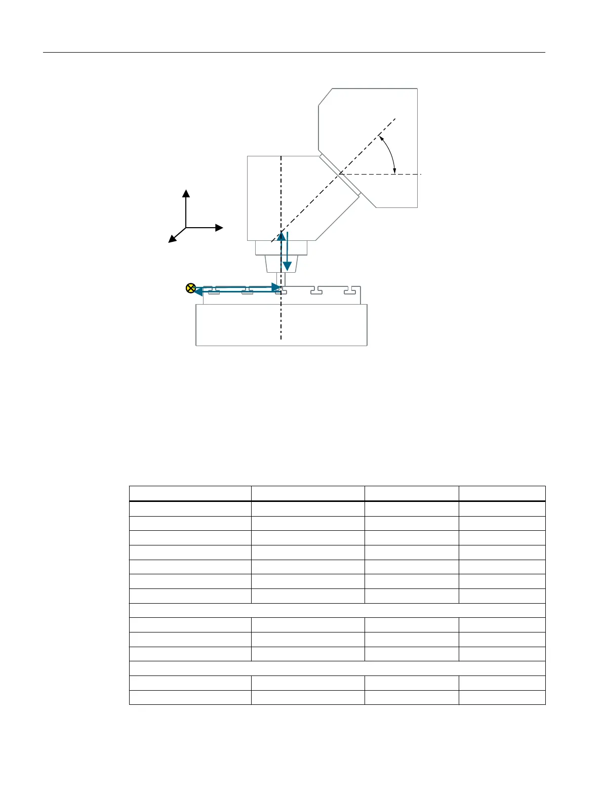
5HIHUHQFHSRLQWRI
WKHPDFKLQH
0.6;<=
5RWDU\D[LV&
5RWDU\D[LV%
=
¡
9
9
O O
<
;
O
O]
O
O\
O O
Rotary axis vector V1 Rotary axis B rotates around Y and around Z.
Rotary axis vector V2 Rotary axis C rotates about Z.
Offset vector I2 The distance from the reference point of the tool adapter to the center of
rotation/intersection of rotary axis 1
Offset vector I1 Closure of vector chain, I1 = - I2.
Offset vector I3 The distance from the reference point of the machine to the center of rotation/
intersection of rotary axis 2.
Offset vector I4 Closure of vector chain, I4 = - I3.
Figure 21-10 Side view of the machine
Kinematics Mixed kinematics MIXED_45
X Y Z
Offset vector I1 0.000 0.000 -30.600
Rotary axis vector V1 0.000 1.000
1)
1.000
1)
Offset vector I2 0.000 0.000 30.600
Offset vector I3 300.000 150.000 0.000
Rotary axis vector V2 0.000 0.000 -1.000
Offset vector I4 -300.000 -150.000 0.000
Display version
Swivel mode Axis-by-axis
Direction Rotary axis 1
Correct tool Yes
Rotary axes
Rotary axis 1 B Mode Auto
Angular range 0.000 180.000
Technologies and cycles
21.7 Swiveling
SINUMERIK Operate (IM9)
584 Commissioning Manual, 12/2017, 6FC5397-1DP40-6BA1
 Loading...


