Kinematics Mixed kinematics MIXED_45
Rotary axis 2 C Mode Auto
Angular range 0.000 360.000
1) Calculation of rotary axis vector:
V1: β = 45 degrees
V1Y= sin(-45)= -0.7071
V1Z= cos(-45)= 0.7071
V1Y and V1Z can be normalized to 1.
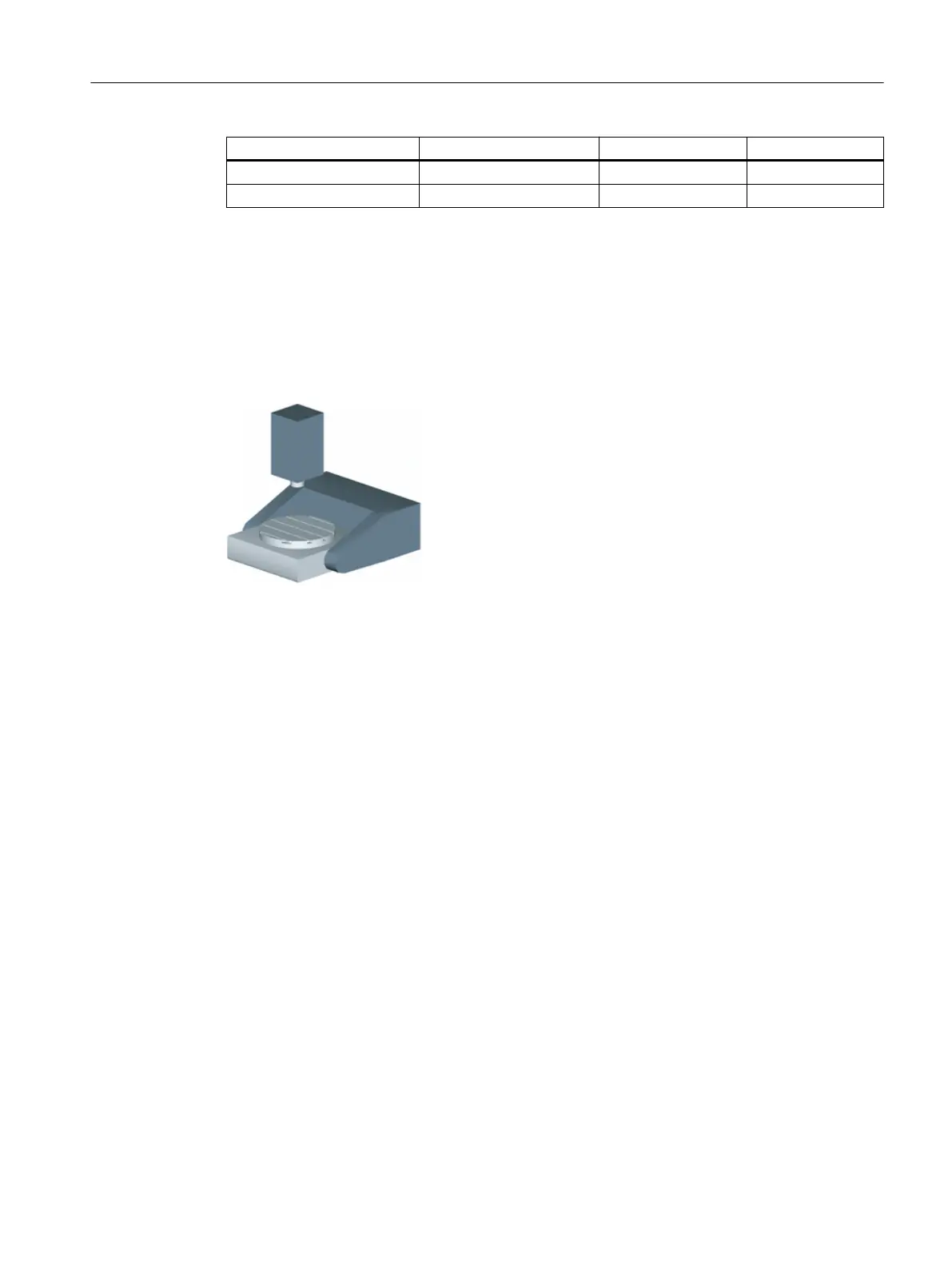
Example 5: Swivel table "TABLE_5"
The vectors in the drawing refer to the initial setting of the kinematics. The spindle (tool adapter)
is positioned on a gage block above the top edge of the table/center of the table (rotary axis
C). A measuring rod in the spindle is used to determine the turning center of rotary axis C.
Technologies and cycles
21.7 Swiveling
SINUMERIK Operate (IM9)
Commissioning Manual, 12/2017, 6FC5397-1DP40-6BA1 585
 Loading...


