Connection
6.3 Connecting the control circuit
100 Manual, 08/2017, L1V30368969104A-02
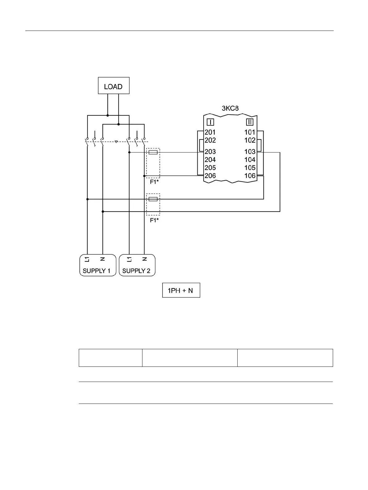
A typical connection of sources I and II (1PH + N) to the electronic module of the 3KC8 is
shown in the circuit diagram below:
* The F1 fuses are not required when using the 3KC9833-, 3KC9834- power supply kits.
Figure 6-87 Circuit diagram for a typical connection of the sources (1PH + N) to the electronic
module
If the power supply kit is not used, the following fuses are to be fitted:
F1 1 x 3NW6004-1
1 x 3NW7013
4 A, gG
The F1 fuses must be installed as closely as possible to the tap.