Connection
6.2 Connecting the main circuit
Manual, 08/2017, L1V30368969104A-02
63
Connecting versions 3 to 6
Versions 3 and 5, as well as versions 4 and 6, are connected to the power supply systems in
two different ways:
● Version 3 and 5: Vertically aligned
● Version 4 and 6: Horizontally aligned
● Main circuit is disconnected
● Transfer switching equipment is in the "Manual" position
● Copper bar connection kit is mounted
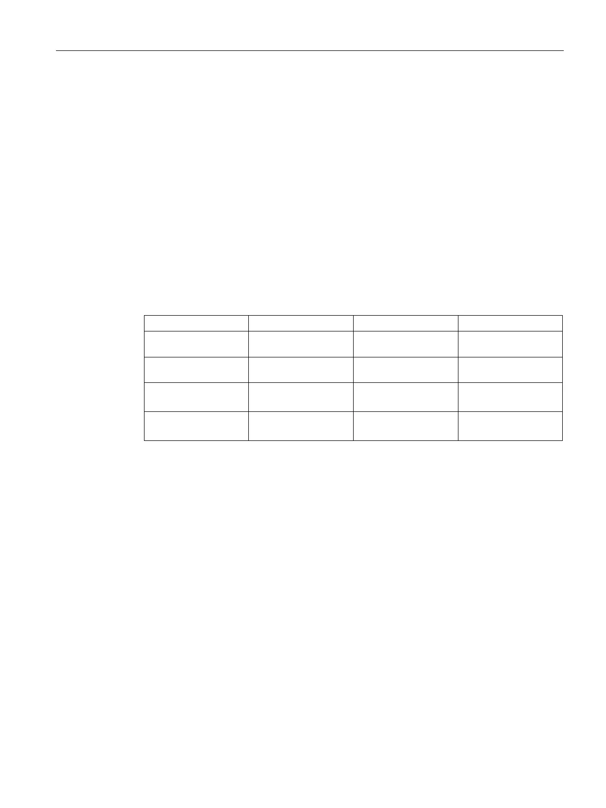
The bolt set required for mounting is not included with the transfer switch. You can find the
bolt set requirements in the following table:
3 (vertical)
2000 … 2500 A
3 x H M12-55 6.8 6 x 3 x
4 (horizontal)
2000 … 2500 A
5 x H M12-55 6.8 10 x 5 x
5 (vertical)
2900 A
3 x H M12-65 6.8 6 x 3 x
6 (horizontal)
3200 A
5 x H M12-65 6.8 10 x 5 x