Connection
6.2 Connecting the main circuit
Manual, 08/2017, L1V30368969104A-02
71
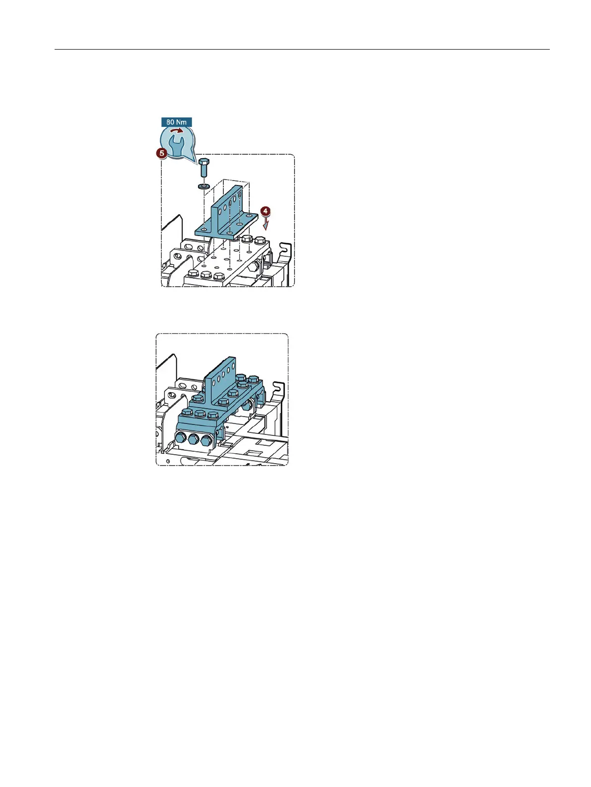
4. Position the T piece, part C (3KC9811-3) as shown in the figure on the mounted bridging
bar.
Figure 6-48 Mounting the T piece
5. Mount the T piece on the bridging bar with the supplied bolts and washers.
Figure 6-49 Mounting copper bar connection kit, versions 9 to 12, complete
Connecting versions 9 to 12
Versions 9 and 11 as well as versions 10 and 12 are connected to the power supply systems
in two different ways:
● Version 9 and 11: Vertically aligned
● Version 10 and 12: Horizontally aligned
The same components are required for versions 9 to 12 as for versions 3 to 6. Mounting is
also identical to mounting of versions 3 to 6.
The following versions correspond here:
● Version 9 corresponds to version 3 (vertical, 2000 A to 2500 A)
● Version 10 corresponds to version 4 (horizontal, 2000 A to 2500 A)
● Version 11 corresponds to version 5 (vertical, 3200 A)
● Version 12 corresponds to version 6 (horizontal, 3200 A)
You will find the installation instructions for versions 3 to 6 in the section titled Connecting
current ratings 250 A to 1600 A to the main circuit (Page 46).