Connection
6.3 Connecting the control circuit
86 Manual, 08/2017, L1V30368969104A-02
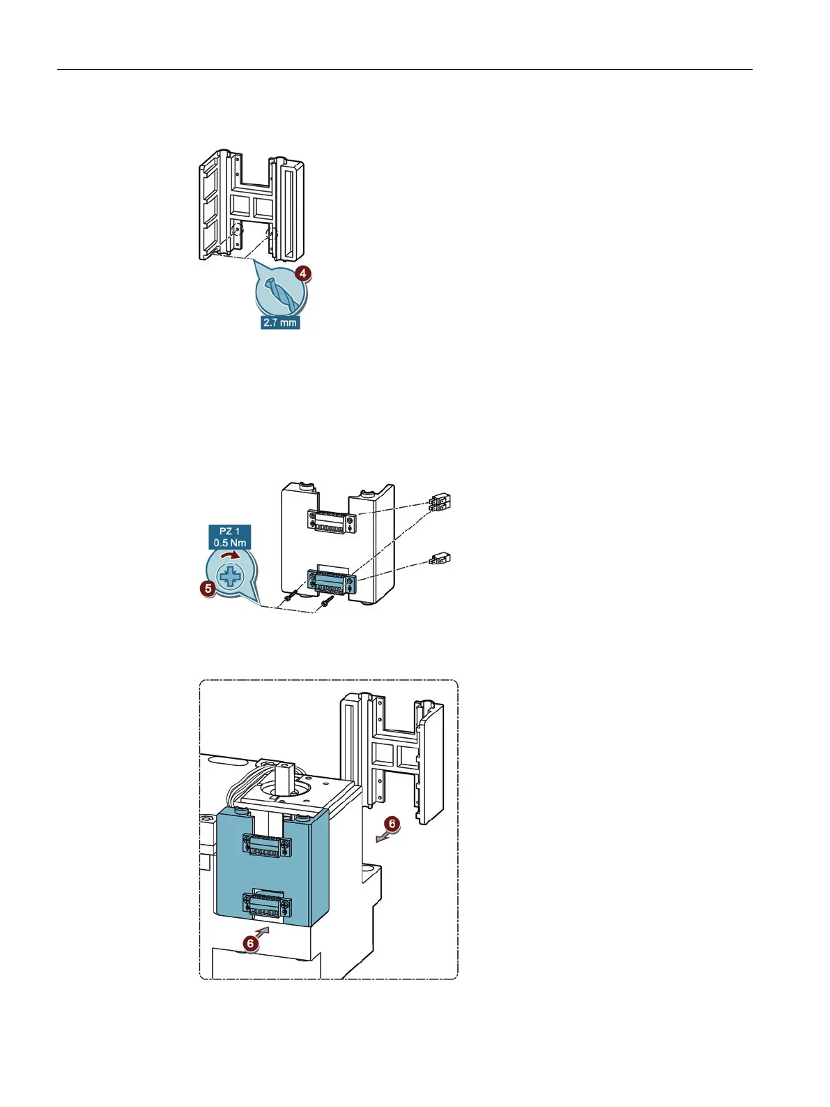
4. Remove the H piece of the transfer switching equipment and drill out the pre-drilled holes.
Figure 6-70 Drilling out H piece
5. Mount the terminal of the auxiliary switch in the H piece in accordance with the figure.
– When installing 1 auxiliary switch, mount the terminal in the lower hollow of the H
piece.
– When installing 2 auxiliary switches, mount the terminals in the lower or upper hollow
of the H piece.
Figure 6-71 Mounting the auxiliary switch terminal on the H piece
6. Secure the H piece again on the transfer switching equipment.
Figure 6-72 Securing H piece