Connection
6.3 Connecting the control circuit
Manual, 08/2017, L1V30368969104A-02
97
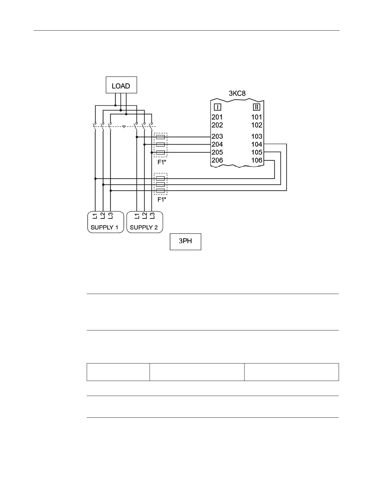
A typical connection of sources I and II (3PH) to the electronic module of the 3KC8 is shown
in the circuit diagram below:
*
The F1 fuses are not required when using the 3KC9822-, 3KC9832- auxiliary conductor terminal
Figure 6-84 Circuit diagram for a typical connection of the sources (3PH) to the electronic module
The complete circuit diagram with connection to the power supply can be found in section
Circuit diagram for the 3KC8 transfer switching equipment - 3-pole transfer switching
equipment (Page 36).
If the auxiliary conductor terminal connection kit is not used, the following fuses are to be
fitted:
F1 3 x 3NW6004-1
1 x 3NW7033
4 A, gG
The F1 fuses must be installed as closely as possible to the tap.