Technical specifications
9.6 KP8 and KP8F - Bit assignment in the process image
KP8, KP8F, KP32F
116 Operating Instructions, 11/2011, A5E03284305-02
9.6 KP8 and KP8F - Bit assignment in the process image
The signal states of HMI device digital inputs/outputs that are used in standard mode are
saved in their own process images independently from the signal states of the fail-safe
channels.
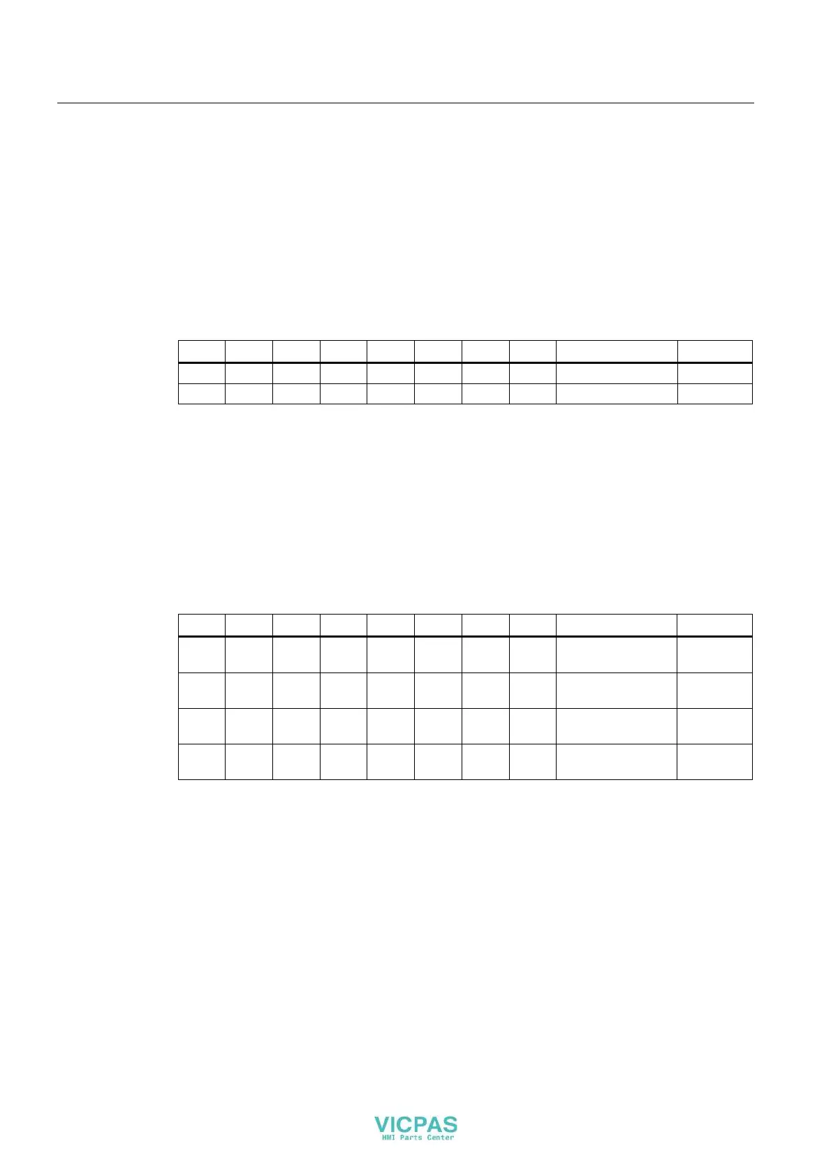
Input area of the controller
The keys and digital inputs of the HMI device are mapped to the bits in the input area of the
controller as follows:
Bit 7 Bit 6 Bit 5 Bit 4 Bit 3 Bit 2 Bit 1 Bit 0 Description Input
K 7 K 6 K 5 K 4 K 3 K 2 K 1 K 0 Keys 0 to 7 Byte 0
DI 7 DI 6 DI 5 DI 4 DI 3 DI 2 DI 1 DI 0 Digital inputs 0 to 7 Byte 1
K = Key
DI = Digital input
The numbering refers to the specifications in the chapter "Front-sided control elements and
di
splays (Page 65)".
Output area of the controller
Each of the three questions has its own output byte. The LEDs are assigned to the bits in the
output area of the controller as follows:
Bit 7 Bit 6 Bit 5 Bit 4 Bit 3 Bit 2 Bit 1 Bit 0 Description Output
R 7 R 6 R 5 R 4 R 3 R 2 R 1 R 0 LEDs 0 to 7,
red
Byte 0
G 7 G 6 G 5 G 4 G 3 G 2 G 1 G 0 LEDs 0 to 7,
green
Byte 1
B 7 B 6 B 5 B 4 B 3 B 2 B 1 B 0 LEDs 0 to 7,
blue
Byte 2
DO 7 DO 6 DO 5 DO 4 DO 3 DO 2 DO 1 DO 0 Digital outputs
0 to 7
Byte 3
R = Red
G = Green
B = Blue
DO = Digital output