Planning the use
3.5 Preparing for Mounting
KP8, KP8F, KP32F
38 Operating Instructions, 11/2011, A5E03284305-02
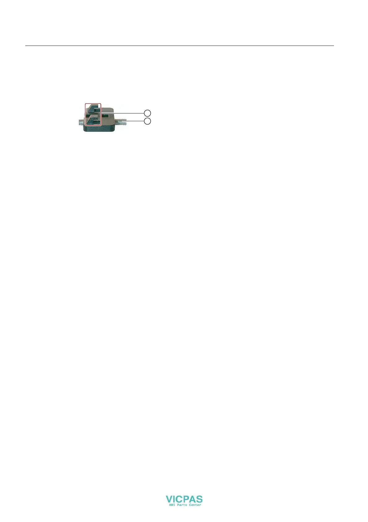
Type of fixation
Mounting clamps are provided for mounting the device - see section "Accessory kit
(Page 17)".
① Hooks
② Grub screw
The main dimensions of the HMI device are not exceed by the installation of the mounting
clamps.
3.5 Preparing for Mounting
Select the HMI device mounting location
Points to observe when selecting the mounting location:
● Position the HMI device so that it is not subjected to direct sunlight.
● Position the HMI device such that it is ergonomically accessible for the user.
Choose a suitable mounting height.
● Ensure that the air vents are not covered as a result of the mounting.
● Observe the permissible mounting positions for the HMI device.
Configuration of the mounting cut-out
In order to guarantee the protective type corresponding with section "Insulation resistance,
protection class and degree of protection (Page 41)", the following must be complied with:
● The material at the mounting cut-out mu
st be distortion-resistant.
● Material thickness at the mounting cutout for IP65 degree of protection or for
enclosure type 4X/type 12 (indoor use only): 2 mm up to 6 mm
● Permitted deviation from plane at the mounting cut-out: ≤ 0.5 mm
This condition must be fulfilled for the mounted HMI device.
● Permissible surface roughness in the area of the seal: ≤ 120 µm (R
z
120)