Mounting and connecting the HMI device
4.4 Connecting the HMI device
KP8, KP8F, KP32F
50 Operating Instructions, 11/2011, A5E03284305-02
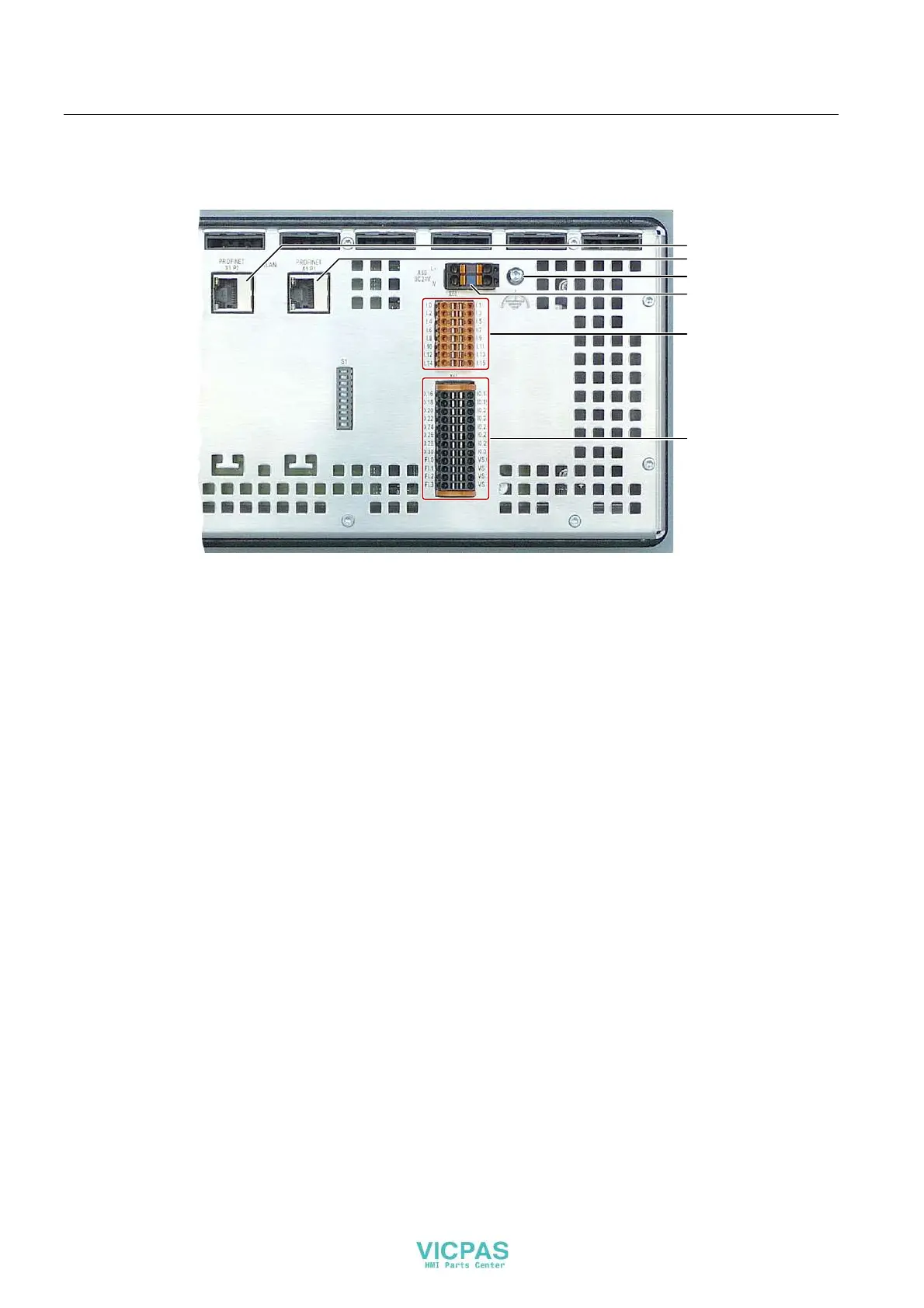
The following figure shows the interfaces of the KP32F.
'LJLWDOLQSXWVRXWSXWV
3RZHUVXSSO\
;3352),1(7
;3352),1(7
)XQFWLRQDOJURXQG
'LJLWDOLQSXWV
4.4.3 Connecting functional grounding at the KP32F
Differences in electrical potential
Differences in potential may occur between spatially separated system parts. Such
differences in electrical potential can lead to high equalizing currents over the data cables
and therefore to the destruction of their interfaces. Equalizing currents can develop if the
cable shielding is terminated at both ends and grounded to different parts of the system.
Differences in potential can develop when a system is connected to different mains.
General requirements of equipotential bonding
Differences in electrical potential must be reduced using equipotential bonding to ensure
trouble-free operation of the relevant components of the electronic system. The following
must therefore be observed when installing the equipotential bonding circuit:
● The effectiveness of equipotential bonding increases as the impedance of the
equipotential bonding conductor decreases or as its cross-section increases.
● If two plant parts are interconnected by means of shielded data cables and their shielding
is bonded at both ends to the grounding/protective conductor, the impedance of the
additionally installed equipotential bonding cable must not exceed 10% of the shielding
impedance.
● The cross-section of a selected equipotential bonding conductor must be capable of
handling the maximum equalizing current.