Mounting and connecting the HMI device
4.4 Connecting the HMI device
KP8, KP8F, KP32F
Operating Instructions, 11/2011, A5E03284305-02
61
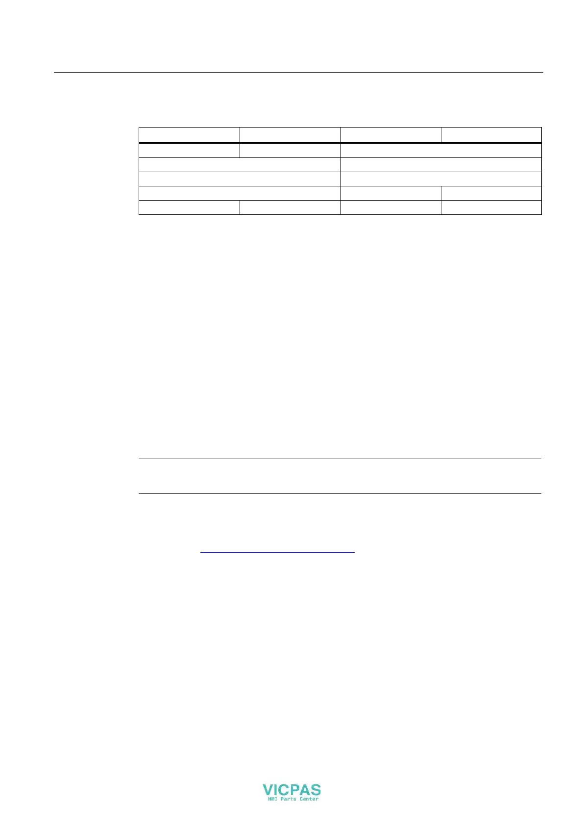
The following connection options are available:
FI.0 FI.1 FI.2 FI.3
1oo1 1oo1 Not connected
1oo2 Not connected
1oo2 1oo2
1oo2 1oo1 1oo1
1oo1 1oo1 1oo1 1oo1
Observe the respective setting for "Evaluation of the sensor" in HW Config - see section
"Setting the fail-safe properties (Page 89)".
4.4.8 Connecting the PLC
The connection between the HMI device and controller depends on the topology of the
PROFINET network.
● Line
All the communication nodes are connected in series as a bus. The series structure is
implemented with switches that are integrated in the PROFINET devices.
● Star
The communication nodes are connected with a switch, from the Scalance X208 or X204
series for example.
You can find additional information on the topology of PROFINET networks in the system
manual, "PROFINET System Description".
Note
Always use only the approved cables to connect a SIMATIC S7 controller.
Standard cables are available for the connection. You will find more information in the
SIMATIC NET-catalog IK PI or on the Internet at:
Industry Mall (http://mall.automation.siemens.com
)