Operator controls and displays
5.2 Rear operator controls and displays
KP8, KP8F, KP32F
66 Operating Instructions, 11/2011, A5E03284305-02
Display elements
The corresponding bit in the controller is set as long as the key is pressed. Surface LEDs are
integrated in each key. They can be used to represent bit states of the connected controller.
The LEDs can be displayed in red, green, yellow, blue and white.
The brightness of the LEDs can be set - see sections "Setting the properties of the digital
inputs/ou
tputs (Page 76)" and "Setting the properties and addresses of the lights and buttons
(Page 85)". The default setting is "normal".
Utilization of the buttons occurs via the process image. See section
"KP8 and KP8F - Bit
assignment in the pro
cess image (Page 116)".
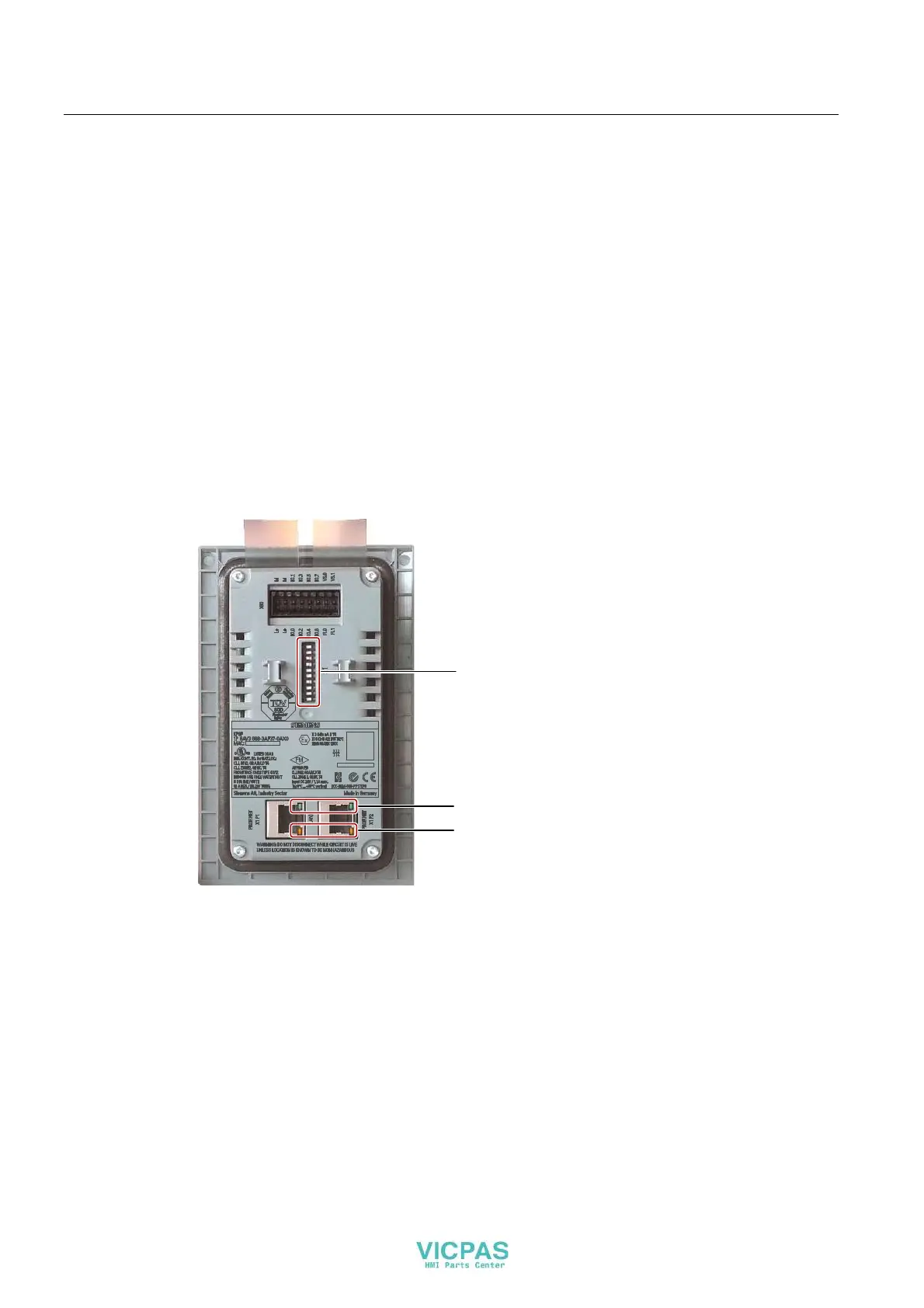
5.2 Rear operator controls and displays
On the rear of the KP8 and the KP8F, you will find the following operator elements and
displays. The DIP switch is only available on the KP8F.
',3VZLWFK
*UHHQ/('
<HOORZ/('