Mounting and connecting the HMI device
4.4 Connecting the HMI device
KP8, KP8F, KP32F
54 Operating Instructions, 11/2011, A5E03284305-02
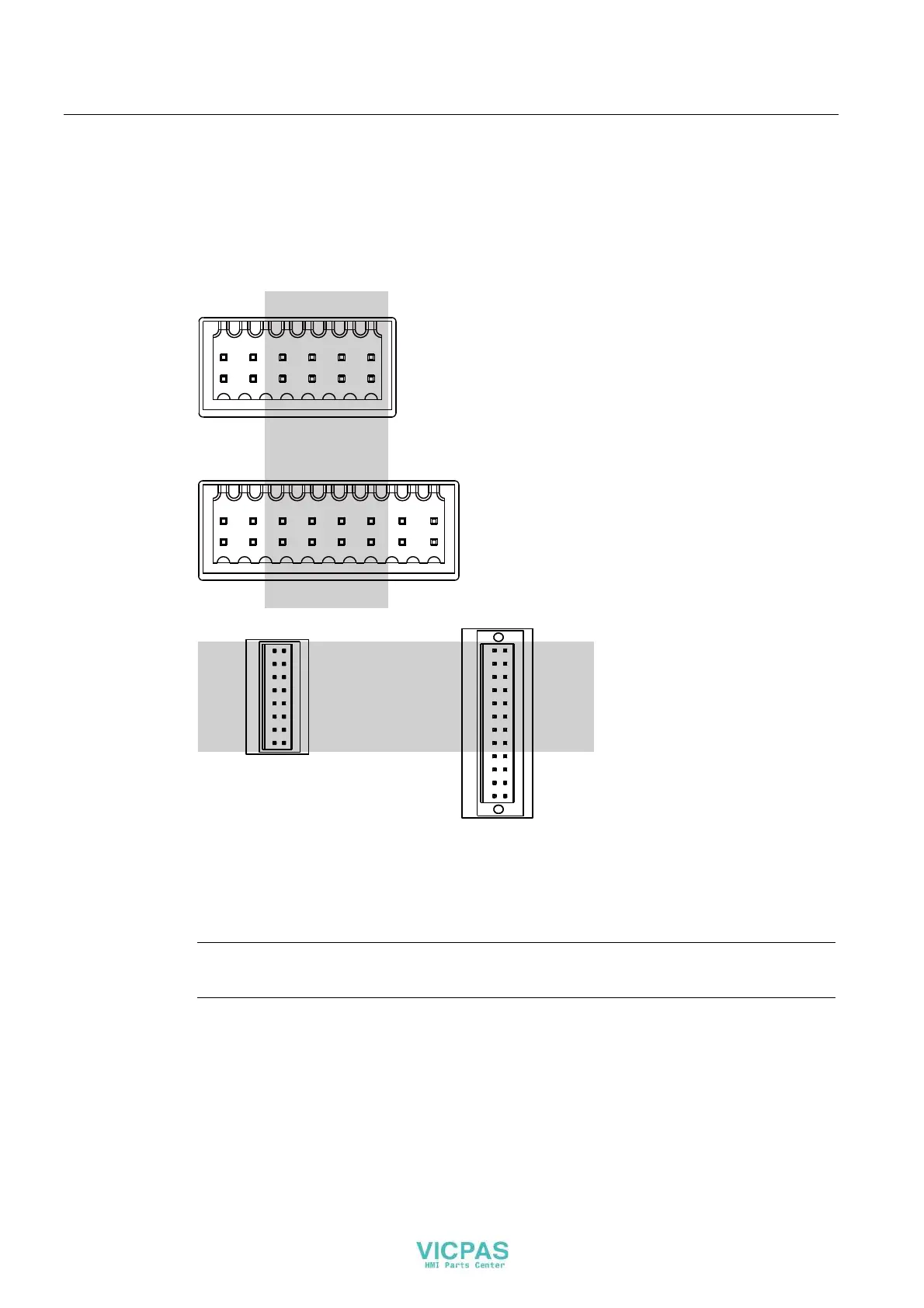
4.4.5 Connect standard inputs/outputs
On the back of the HMI device are the digital inputs/outputs for non fail-safe input and output
devices. Non fail-safe inputs/outputs are shown in gray in the following illustrations.
Unconnected inputs/outputs are automatically set to "0".
,2 ,2,2,2
,2 ,2,2,2
,2 ,2,2,2
,2 ,2,2,2
.3
;
.3)
;
,2
,2
,2
,2
,2
,2
,2
,2
,2
,2
,2
,2
,2
),
,2
,2
),
),
),
96
96
96
96
,2
;
,
,
,
,
,
,
,
,
,
,
,
,
,
,
,
,
;
.3)
The signal assignment is described in the section "Interface description (Page 112)".
Procedure
Note
Follow the notes about connectors in section "Connecting the power supply (Page 52)".
1. Connect the wires on the connector corresponding with the setting of the socket on the
rear of the HMI device.