Technical specifications
9.8 KP32F - Bit assignment in the process image
KP8, KP8F, KP32F
Operating Instructions, 11/2011, A5E03284305-02
119
9.8 KP32F - Bit assignment in the process image
The signal states of HMI device digital inputs/outputs that are used in standard mode are
saved in their own process images independently from the signal states of the fail-safe
channels.
Input area of the controller
See figure in section "Front-sided control elements and displays (Page 65)". The keys and
digital inputs of the HMI device are mapped to the bits in the input area of the controller as
follows:
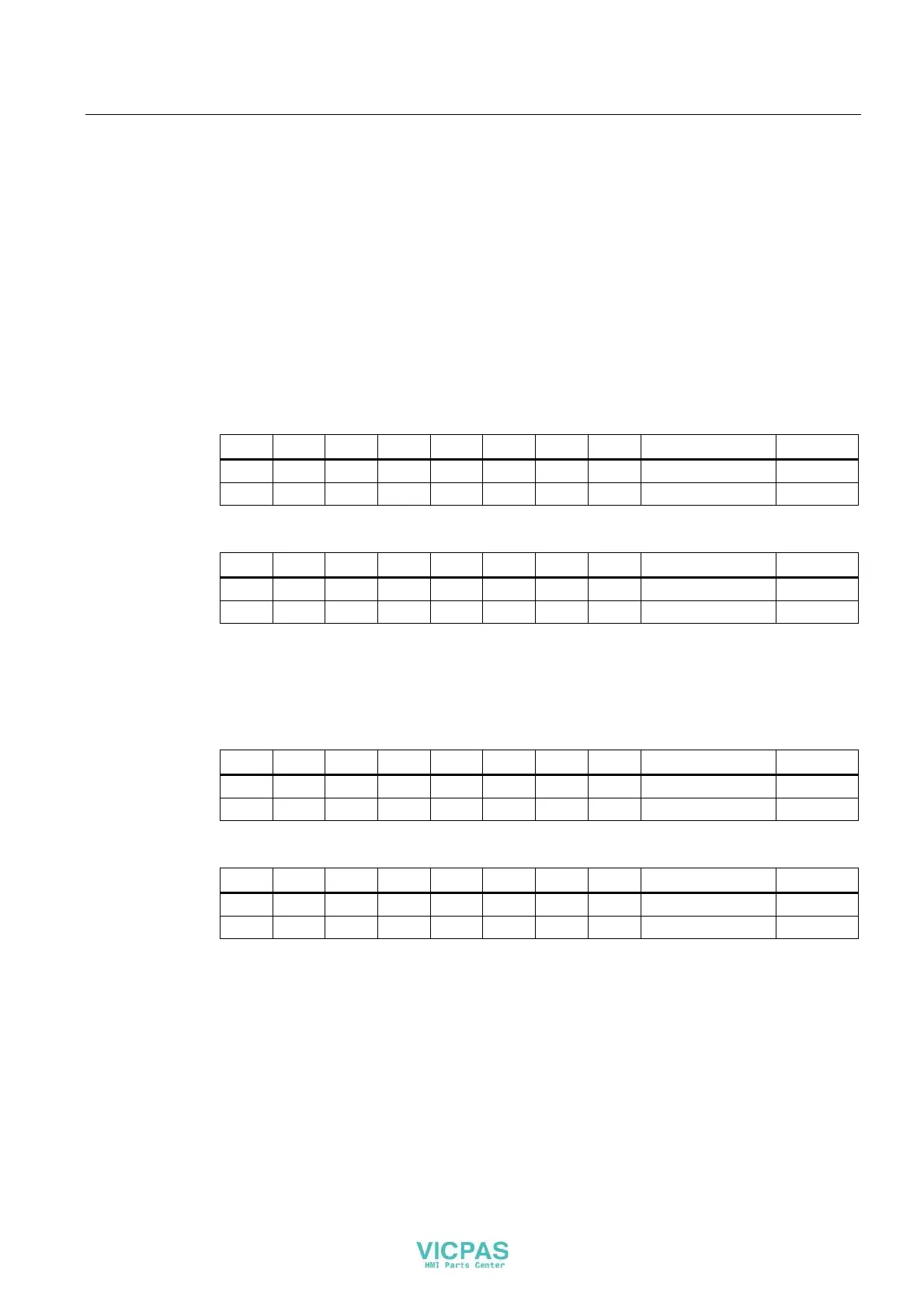
Input area, slot 1
Bit 7 Bit 6 Bit 5 Bit 4 Bit 3 Bit 2 Bit 1 Bit 0 Description Input
K07 K06 K05 K04 K03 K02 K01 K00 Keys 0 to 7 Byte 0
K15 K14 K13 K12 K11 K10 K09 K08 Keys 8 to 15 Byte 1
Input area, slot 2
Bit 7 Bit 6 Bit 5 Bit 4 Bit 3 Bit 2 Bit 1 Bit 0 Description Input
K23 K22 K21 K20 K19 K18 K17 K16 Keys 16 to 23 Byte 0
K31 K30 K29 K28 K27 K26 K25 K24 Keys 24 to 31 Byte 1
K = Key
The numbering of the keys refers to the specifications in the section "Front-sided control
elements and
displays (Page 65)".
Digital inputs, slot 3
Bit 7 Bit 6 Bit 5 Bit 4 Bit 3 Bit 2 Bit 1 Bit 0 Description Input
DI07 DI06 DI05 DI04 DI03 DI02 DI01 DI00 Input 0 to 7 Byte 0
DI15 DI14 DI13 DI12 DI11 DI10 DI09 DI08 Input 8 to 15 Byte 1
Digital inputs, slot 4
Bit 7 Bit 6 Bit 5 Bit 4 Bit 3 Bit 2 Bit 1 Bit 0 Description Input
DI23 DI22 DI21 DI20 DI19 DI18 DI17 DI16 Input 16 to 23 Byte 0
DI31 DI30 DI29 DI28 DI27 DI26 DI25 DI24 Input 24 to 31 Byte 1
DI = Digital input